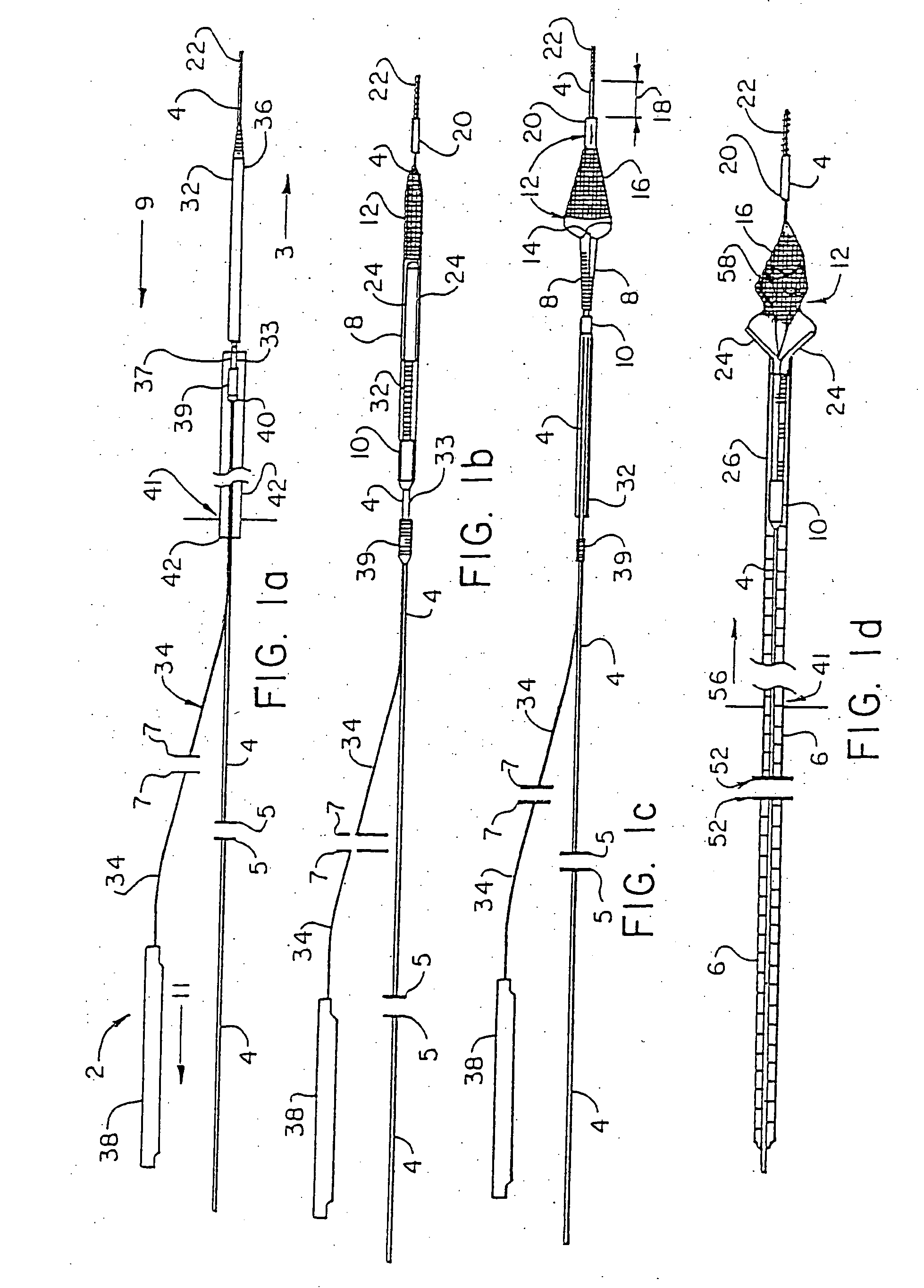
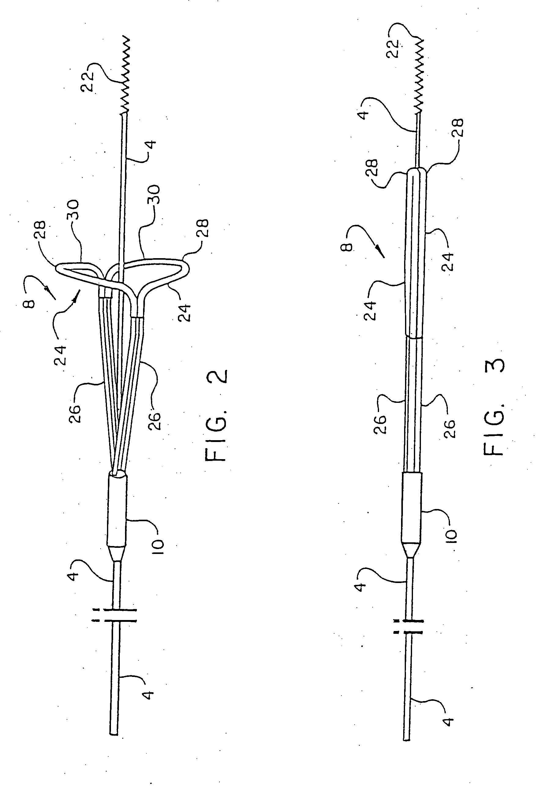
However, this therapy is complicated by the fact that it can undesirably dislodge or free particles / objects during the procedure as discussed above, and in that the tools or instruments and
workspace, e.g., the interior of the vessels of the body, are in some cases extremely small and close, and reaching the operative site with the tools is very difficult in some instances due to the considerable branching of the
circulatory system that may occur between the
entry site into the
blood vessel and the operative site.
This therapy is further complicated by the fact that the
entry site is often far from the operative site, as for example, where the
entry site is in the
thigh at the
femoral artery and the operative site is located in the neck at the carotid
artery.
Even when the surgeon's instruments have been properly advanced to the operative site, manipulating the tools to perform their respective functions at the operative site is often difficult for the surgeon due to many factors including the close quarters at the operative site and the distance between the entry site and the operative site.
A lack of correlation between rotation at the proximal region of the guide wire and rotation at the distal end of the guide wire is referred to as reduced torquability and is undesirable.
With known devices, there is considerable difference between the amount of rotation applied at the proximal region of the guide wire and the amount of rotation developed at the distal end of the guide wire, making it very difficult for surgeons to maneuver the distal end of the guide wire.
Even where the guide wire exhibits the desired torquability characteristics, and the tools have been properly threaded to the operative site and have been properly manipulated to perform their respective functions at the operative site, there remains the problem noted above, namely, that the process of dilating the
occlusion and / or inserting the
stent may dislodge or free
small particles or objects, also known, among other things, as clots, fragments, plaque, emboli, thromboemboli, etc.
This is most undesirable and can lead to many complications.
Complications depend upon the site in the body where such emboli lodge downstream of the operative site, but may include
stroke,
myocardial infarction,
kidney failure, limb loss or even death.
An important limitation of the Wholey et al. device appears to be that the filter does not seal around the interior vessel wall.
Thus, particles sought to be trapped in the filter can instead undesirably pass between the filter and the vessel wall and flow downstream in the
circulatory system to produce a blockage.
Another limitation is that the device also presents a large profile during positioning.
Yet another limitation appears to be that the device is difficult to construct.
Again, however, it appears that the filter does not seal around the interior vessel wall, thus undesirably allowing particles to bypass the filter by passing between the filter and the vessel wall.
The position of the mouth relative to the sheath is also clinically limiting for the Ginsburg device.
One limitation with the Summers et al. device appears to be that its
filter material is not fully constrained.
Therefore, during positioning within a vessel, as the device is positioned through and past a clot, the
filter material can snag clot material undesirably creating freely floating emboli.
Another limitation appears to be that the device application is limited by the
diameter of the tube needed to contain the actuating wire.
One limitation of the device appears to be that during positioning, as the device is passed through and beyond the clot,
filter material may interact with the clot so as to undesirably dislodge material and produce emboli.
It is further believed that the device may also be difficult to manufacture.
Another limitation is that it is difficult to determine the amount of fluid needed to expand the member.
A lack of control can rupture and tear the smaller vessels.
A limitation of this device appears to be that the filter does not seal around the interior vessel wall.
Thus, particles, e.g., emboli-forming materials, can undesirably bypass the filter by passing between the filter and the vessel wall.
Another limitation appears to be that this umbrella-type device is shallow when deployed so that, as it is being closed for removal, the particles it was able to ensnare could escape.
Yet another limitation is that the frame is such that the introduction profile presents a risk of generating emboli as the device is passed through and beyond the clot,
occlusion or
stenosis.
Limitations of this device include that it is complex to manufacture.
Inflation and deflation of the seal adds additional operative steps thus prolonging the operation and introducing the issue again of control, e.g., of how much to inflate to obtain a seal without causing damage to the vessel or other material.
While the device may be suitable for large vessels, such as the
aorta, is would be most difficult to scale for smaller vessels, such as the carotid or the
coronary arteries.
One limitation of this device appears to be that it is possible that some particles will remain in the filter after aspiration such that, when the filter is retracted into the outer
catheter, particles not aspirated are undesirably released into the
circulatory system.
One limitation of the Tsugita et al. device is that the many filter designs summarized in the patent generally lack a controllable, conformable circumferential support in the mouth of the filters to ensure they seal around the inside of a
blood vessel.
These are not desirable as they increase the profile of the device when crossing a
lesion, in turn, reducing the range of clinical cases on which they can be used.
Further, such designs add stiffness to the region of the undeployed filter which can impede the surgeon's ability to direct the guide wire through the complex twists and turns of the circulatory
system to the operative site, e.g., making it difficult to direct the device into a branching vessel.
Also, the Tsugita et al. design is burdened by its use of a long deployment sheath to hold the filter in a collapsed state and direct it to the operative site.
This long sheath, necessary in the Tsugita et al. design, significantly impairs the ability to direct the guide wire through the circulatory
system to the operative site.
Not only is such a sheath an impairment to directing the guide wire around the twists and turns of the circulatory
system, but such a sheath also “loads” the guide wire, which operates to significantly reduce the Tsugita et al. system's torquability, greatly reducing the ability of the surgeon to control the guide wire and guide it through tight lesions.
(see column 9, lines 55-58 of the Tsugita et al. patent) However, this is not accurate, and depending upon the type of
stent, not only will it not trap such plaque, but plaque can reform through the interstices of the mesh whereupon the vessel can again become fully or partially occluded.
However, the presently available capture devices all suffer from the limitation that they are not easily manipulated in the patient's body.
Removal without causing excessive movement of the deployed filter is also a problem.
As the surgeon's hand grasps the wire further from the
access port, the more difficult it becomes to steady the guide wire as the sheath is withdrawn.
As such, the capture device may move back and forth, and as it is generally at this point in its expanded state, the constant
rubbing of the wall of the blood or other vessel or canal by the capturing device may irritate or injure the wall of the blood or other vessel or canal.
Another complication is that several capture devices include bulky or complex deployment mechanisms, and further, when deployed, fail to fully seal around the interior of the vessel or other wall or fail to prevent unwanted release of captured particles, fragments, objects, emboli, etc., whereupon such particles, fragments, objects, emboli, etc. can undesirably escape and travel beyond the capture device.


