Hemostasis pad and method

a technology of hemostasis pad and hematoma, which is applied in the field of hemostasis medical devices, can solve the problems of prolonging clotting time and complicated situation, and achieve the effect of reducing the time period required and reducing the likelihood of hematoma

Inactive Publication Date: 2005-10-06
LEVINSON MELVIN
View PDF0 Cites 7 Cited by
  • Summary
  • Abstract
  • Description
  • Claims
  • Application Information

AI Technical Summary

Benefits of technology

[0009] The use of a positive charge administered by either cationic substances or by iontophoretic means to quickly create a coagulation process and hemostasis until the normal clotting cascade can take over. This can occur even in the face of significant anticoagulation since the process is ionic and not effected by the anticoagulants, which operate on the normal blood cascade. This approach can be revolutionary in the after treatment of patients with minimally invasive or invasive procedures since rapid hemostasis and mobilization of the patient are desirable endpoints.
[0013] According to one aspect of the present invention, a hemostatic pad defines an opening at an approximately central point of the pad. The opening is sized to allow egress of the indwelling tubular element through the pad. The pad further comprises an application surface which contains hemostatic agent used for stopping the bleeding at the wound site associated with an indwelling tubular element. The hemostatic agent preferably is a cationic substance, such as cationic polymer, or a cationic protein. The pad, with the indwelling tubular element passing through the opening of the pad, provides an even application of pressure to the wound site. The hemostatic substance on the pad, therefore, may be applied evenly, directly and intimately to the wound site around the tubular element. It also allows the indwelling tubular element to be easily removed from the wound site through the pad. In a preferred embodiment, the opening of the pad is a slit extending from an approximate center to an edge of the pad. In another preferred embodiment, the opening is constructed as an aperture with an elongated cut extending from the aperture to an edge of the pad. In one preferred form, the slit or the elongated cut is at a bias angle with respect to the central region of the pad.
[0014] According to another aspect of the present invention, the hemostatic pad may have a non-slip etched area on a top surface of the pad, in order to achieve more friction between the finger of a surgeon and the surface of the pad. The non-slip etched area make it easier to apply a pressure to a puncture site, and make the hemostasis more efficiently and quickly.
[0018] The present invention provides many benefits, including reducing the time period required to stop bleeding at a puncture wound and decreasing the likelihood that a hematoma will form particularly, but not limited to, cases following removal of an introducer, a catheter or a tube from the puncture wound. These and other features and benefits of the present disclosure will become more apparent upon reading the following specification in combination with the accompanying drawing figures.

Problems solved by technology

The situation is complicated further by the use of anticoagulants in these procedures, which prolongs clotting times. Substances such as heparin, aspirin, coumadin, and other anticoagulants are used with regularity and affect the normal blood coagulation cascade.

Method used


Image

  • Hemostasis pad and method
  • Hemostasis pad and method
  • Hemostasis pad and method

Examples


Embodiment Construction

[0027] The present invention is described hereinafter with specific references to the use of the present invention for sealing an incision or puncture wound with an indwelling tubular element, such as catheter, introducer or tube, through the incision or puncture wound. It is contemplated that the present invention may be used with any catheterization or other medical procedure such as laparoscopic or other minimally or less invasive surgeries wherein it is desirable to seal an incision or puncture wound in the patient to prevent the loss of the patient's body fluid therethrough.

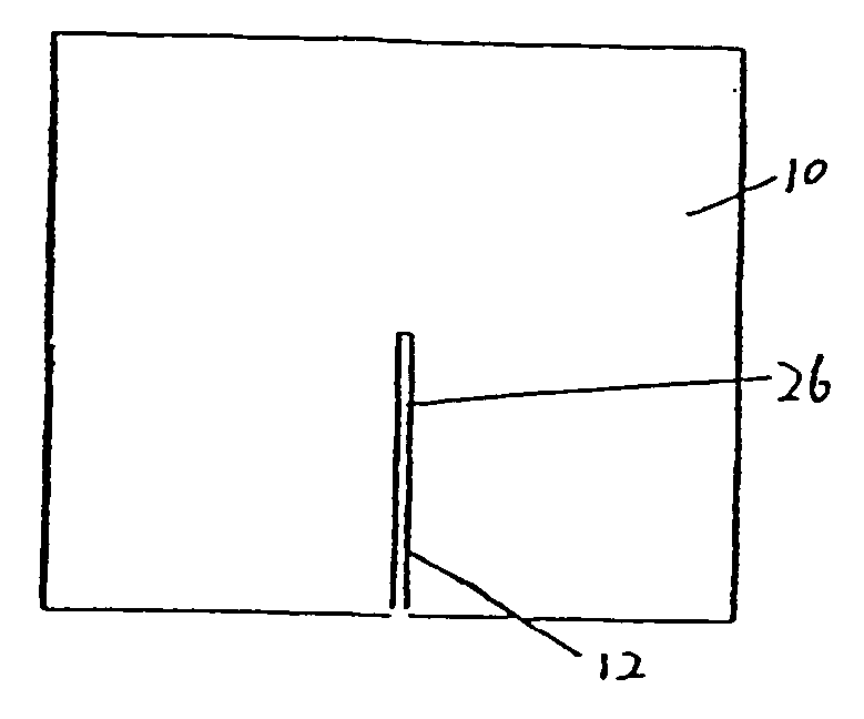
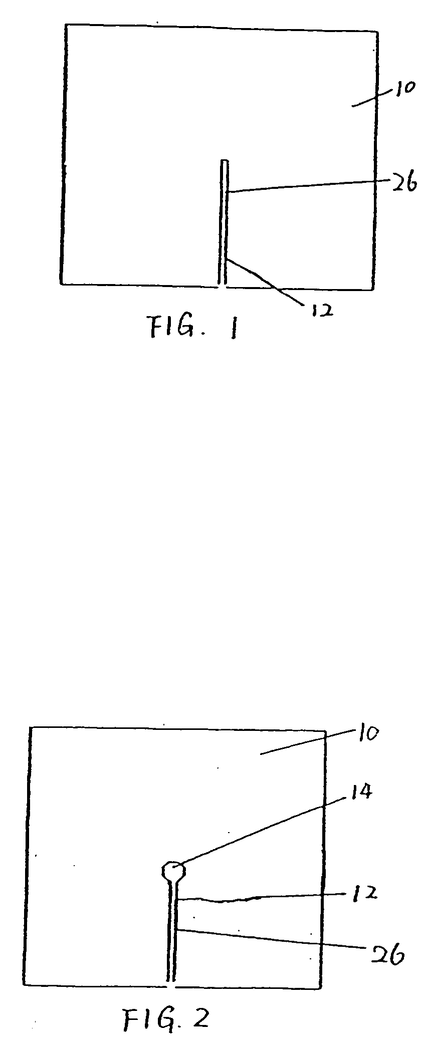
[0028]FIG. 1 is a top view of one preferred embodiment of the present inveniton. Referring to FIG. 1, a pad 10 defines an opening 12 through the pad 10. In a preferred embodiment, the opening is constructed as a slit or an elongated cut 26. As shown in FIG. 1, the slit 26 extends from an approximately central point to an edge of the pad 10. The slit is preferably sized to permit egress of an indwelling tubu...


PUM

PropertyMeasurementUnit
bias angleaaaaaaaaaa
angleaaaaaaaaaa
bias angleaaaaaaaaaa

Abstract

The present invention relates generally to medical devices for applying hemostatic composition to a puncture or wound site with indwelling tubular element, such as catheter, introducer or tube therein, particularly a hemostatic pad with an opening therethrough in order to allow egress of the indwelling tubular element through the hemostatic pad as the hemostatic pad provide hemostasis at the hemorrhaging site. The device may be applied to, or removed from, the wound site while the tubular element is in place. A method for effecting hemostasis at a puncture wound, includes applying pressure proximal to the puncture wound, and directing a cationic biopolymer of glucosamine application surface of a closure pad against the puncture wound with force sufficient to prevent fluid from exiting the puncture wound. Then the pressure proximal to the puncture wound is removed and the force on the closure pad is maintained for at least a first predetermined time period. The force on the closure pad is removed if hemostasis is verified. The puncture wound may then be dressed over the closure pad, and the dressing and the closure pad removed after a second predetermined time period.

Description

REFERENCE TO RELATED APPLICATION [0001] This application is a continuation in part of U.S. patent application Ser. No. 10 / 008,052, filed Nov. 13, 2001, the disclosure of which is incorporated herein by reference.FIELD OF THE INVENTION [0002] The present invention relates to medical devices for hemostasis, and methods of using the medical devices for hemostasis. More particularly, the present invention relates to medical devices for effecting hemostasis at a puncture wound with an indwelling tubular element extending therethrough. BACKGROUND OF THE INVENTION [0003] Puncture of blood vessels is a necessary stage in many of the minimally invasive approaches to diagnosis and treatment, including interventional radiology and cardiology. Therefore, a need to create hemostasis as rapidly as possible following the procedure becomes an important priority. [0004] Various hemostatic agents, such as synthetic or natural cationic polymers, hydrogels, collagen based products, oxidized cellulose, ...

Claims


Application Information

Patent Timeline
Patent Type & Authority Applications(United States)
IPC IPC(8): A61F13/00A61B17/04A61B17/50A61BA61K31/715A61D1/00A61B17/08
CPCA61B17/0057A61F13/00A61F2013/00412A61F2013/00472A61K31/715A61L2400/04
Inventor LEVINSON, MELVIN
Owner LEVINSON MELVIN
Why Eureka
Try Eureka