Cloosed-loop feedback-driven neuromodulation

a feedback-driven, neuromodulation technology, applied in the field of neurodegenerative diseases, can solve the problems of moderate efficacy, procedures suffer from a number of fundamental limitations, and can not be moderately effective, so as to reduce the time and number of interactions, enhance the manual selection of the optimum treatment magnitude, and optimize the energy utilization

Inactive Publication Date: 2005-10-06
CYBERONICS INC
View PDF99 Cites 127 Cited by
  • Summary
  • Abstract
  • Description
  • Claims
  • Application Information

AI Technical Summary

Benefits of technology

[0028] Another advantage of certain aspects of the present invention is that it performs automated determination of the optimum magnitude of treatment. By sensing and quantifying the magnitude and frequency of tremor activity in the patient, a quantitative representation of the level or “state” of the disease is determined. The disease state is monitored as treatment parameters are automatically varied, and the local or absolute minimum in disease state is achieved as the optimal set of stimulation parameters is converged upon. The disease state may be represented as a single value or a vector or matrix of values; in the latter two cases, a multi variable optimization algorithm is employed with appropriate weighting factors. Automated optimization of treatment parameters expedites achievement of satisfactory treatment of the patient, reducing the time and number of interactions, typically in physician visits, endured by the patient. This optimization includes selection of electrode polarities, electrode configurations stimulating parameter waveforms, temporal profile of stimulation magnitude, stimulation duty cycles, baseline stimulation magnitude, intermittent stimulation magnitude and timing, and other stimulation parameters.
[0029] Another advantage of certain aspects of the present invention is its provision of signal processed sensory feedback signals to clinicians to augment their manual selection of optimum treatment magnitude and pattern. Sensory feedback signals provided to the clinician via a clinician-patient interface include but are not limited to tremor estimates, electromyography (EMG) signals, EEG signals, accelerometer signals, acoustic signals, peripheral nerve signals, cranial

Problems solved by technology

These treatment modalities are moderately efficacious; however, they suffer from several severe drawbacks.
This commonly results in alternation between “on” and “off” periods during which the patient possesses and loses motor functionality, respectively.
These procedures have been found to be moderately efficacious.
However, in addition to posing risks that are inherent to neurosurgical operations, these procedures suffer from a number of fundamental limitations.
One such limitation is that tissue removal or destruction is irreversible.
As a result, excessive or inadvertent removal of tissue cannot be remedied.
Furthermore, undesirable side effects, including compromise of vision and motor or sensory functions, are likely to be permanent conditions.
In particular, bilateral interventions place the patient at considerable risk for developing permanent neurologic side effects, including incontinence, aphasia, and grave psychic disorders.
An additional drawback to this approach is that the “magnitude” of treatment is constant.
That is, it is not possible to vary treatment intensity over time, as may be required to match circadian, postprandial, and other fluctuations in symptomatology and consequent therapeutic needs.
Thus, decrease in treatment “magnitude” is not possible while an increase in treatment “magnitude” necessitates reoperation.
Some adjustment is possible through augmentation with pharmacologic treatment; however, these additional treatments are subject to the above-noted limitations related to drug therapy.
Although tissue transplantation in humans has been performed for many years, it remains experimental and is limited by ethical concerns when performed using a human source.
Furthermore, graft survival, as well as subsequ

Method used


Image

  • Cloosed-loop feedback-driven neuromodulation
  • Cloosed-loop feedback-driven neuromodulation
  • Cloosed-loop feedback-driven neuromodulation

Examples


Embodiment Construction

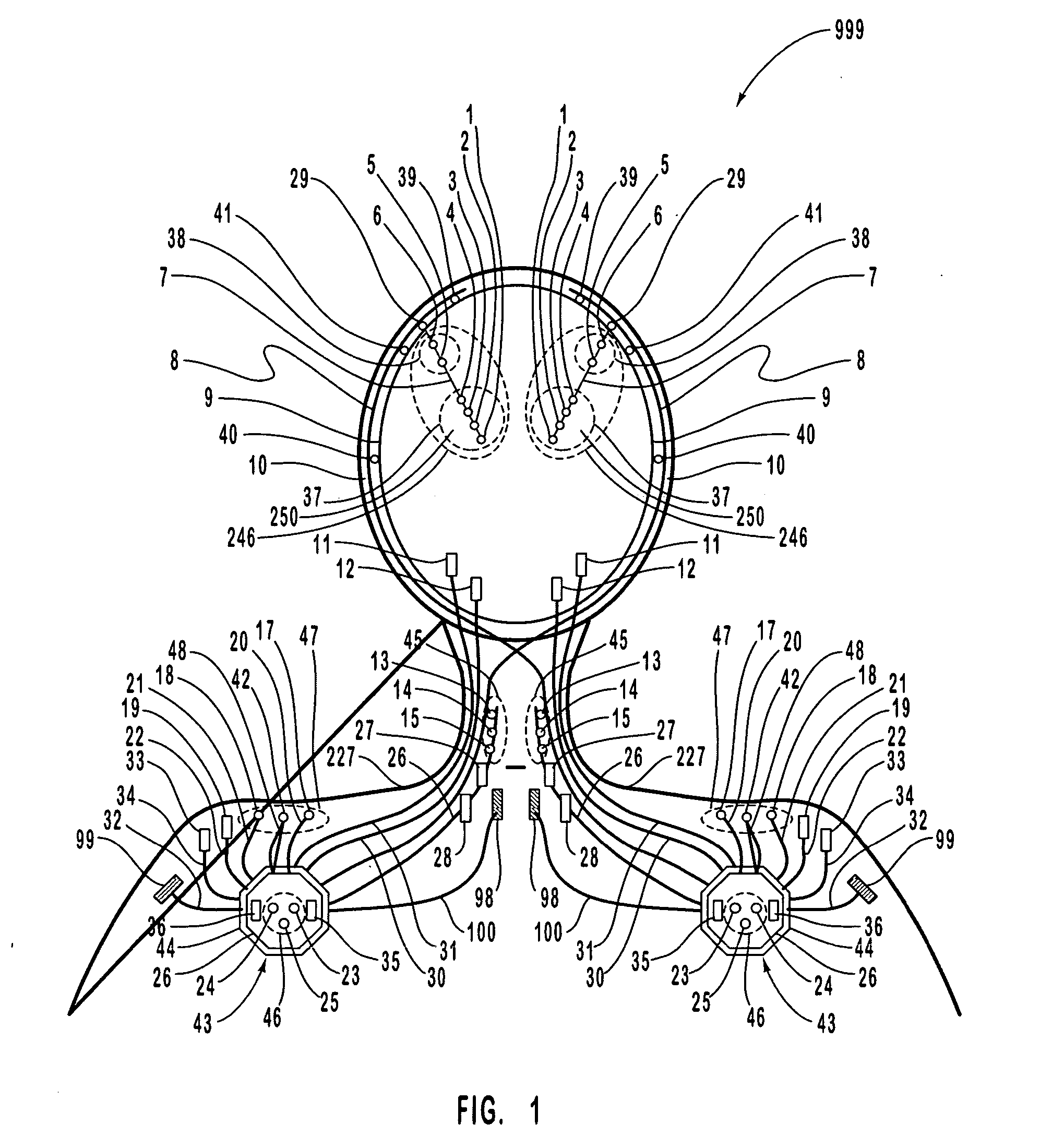
[0052]FIG. 1 is a schematic diagram of one embodiment of the intracranial stimulator of the present invention implanted bilaterally in a human patient. In the embodiment illustrated in FIG. 1, two neurological control systems 999 are shown implanted bilaterally. Each system 999 includes a stimulating and recording unit 26 and one or more intracranial components described below. As described in this illustrative embodiment, the intracranial components preferably include a stimulating electrode array 37. However, it should become apparent to those of ordinary skill in the relevant art after reading the present disclosure that the stimulating electrodes may also be extracranial; that is, attached to a peripheral nerve in addition to or in place of being located within the cranium. As shown in FIG. 1, stimulating and recording unit 26 of each neurological control system 999 is preferably implanted contralateral to the intracranial components of the device.

[0053] As one skilled in the r...


PUM


Abstract

A neurological control system for modulating activity of any component or structure comprising the entirety or portion of the nervous system, or any structure interfaced thereto, generally referred to herein as a “nervous system component.” The neurological control system generates neural modulation signals delivered to a nervous system component through one or more neuromodulators, comprising intracranial (IC) stimulating electrodes and other actuators, in accordance with treatment parameters. Such treatment parameters may be derived from a neural response to previously delivered neural modulation signals sensed by one or more sensors, each configured to sense a particular characteristic indicative of a neurological or psychiatric condition.

Description

CROSS REFERENCE TO RELATED APPLICATIONS [0001] This application is a continuation-in-part of prior, co-pending U.S. patent application Ser. No. 10 / 858,899, entitled CLOSED-LOOP FEEDBACK-DRIVEN NEUROMODULATION, filed Jun. 1, 2004, and naming as inventor Daniel John DiLorenzo. [0002] This application is a continuation in part of prior, co-pending U.S. patent application Ser. No. 10 / 889,844, filed Jul. 12, 2004. [0003] U.S. patent application Ser. No. 10 / 889,844, filed Jul. 12, 2004, is a continuation of prior, co-pending (under 35 U.S.C. 119(e)(3)) U.S. Provisional Application Ser. No. 60 / 562,487 filed Apr. 14, 2004. [0004] U.S. patent application Ser. No. 10 / 889,844, filed Jul. 12, 2004, is a continuation in part of prior, co-pending U.S. patent application Ser. No. 10 / 818,333, filed Apr. 5, 2004, which is a continuation and of prior, co-pending (under 35 U.S.C. 119(e)(3)) U.S. Provisional Application Ser. No. 60 / 460,140 filed Apr. 3, 2003. [0005] U.S. patent application Ser. No. 10 / ...

Claims


Application Information

Patent Timeline
IPC IPC(8): A61N1/08H03C3/06A61N1/36
CPCA61N1/0529A61N1/0531A61N1/0534A61N1/3605A61N1/36082A61N1/36064A61N1/36067
Inventor DILORENZO, DANIEL JOHN
Owner CYBERONICS INC
Why Eureka
Try Eureka