Stent-graft with graft to graft attachment

a technology of graft and stent, applied in the field of stent assembly with graft layers, can solve the problems of patient death, internal hemorrhaging, and so much bleeding

Active Publication Date: 2005-10-06
COOK MEDICAL TECH LLC
View PDF7 Cites 83 Cited by
  • Summary
  • Abstract
  • Description
  • Claims
  • Application Information

AI Technical Summary

Benefits of technology

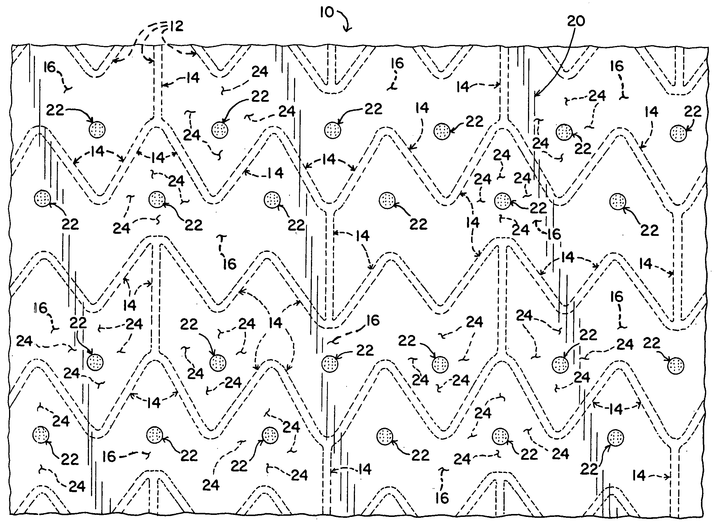
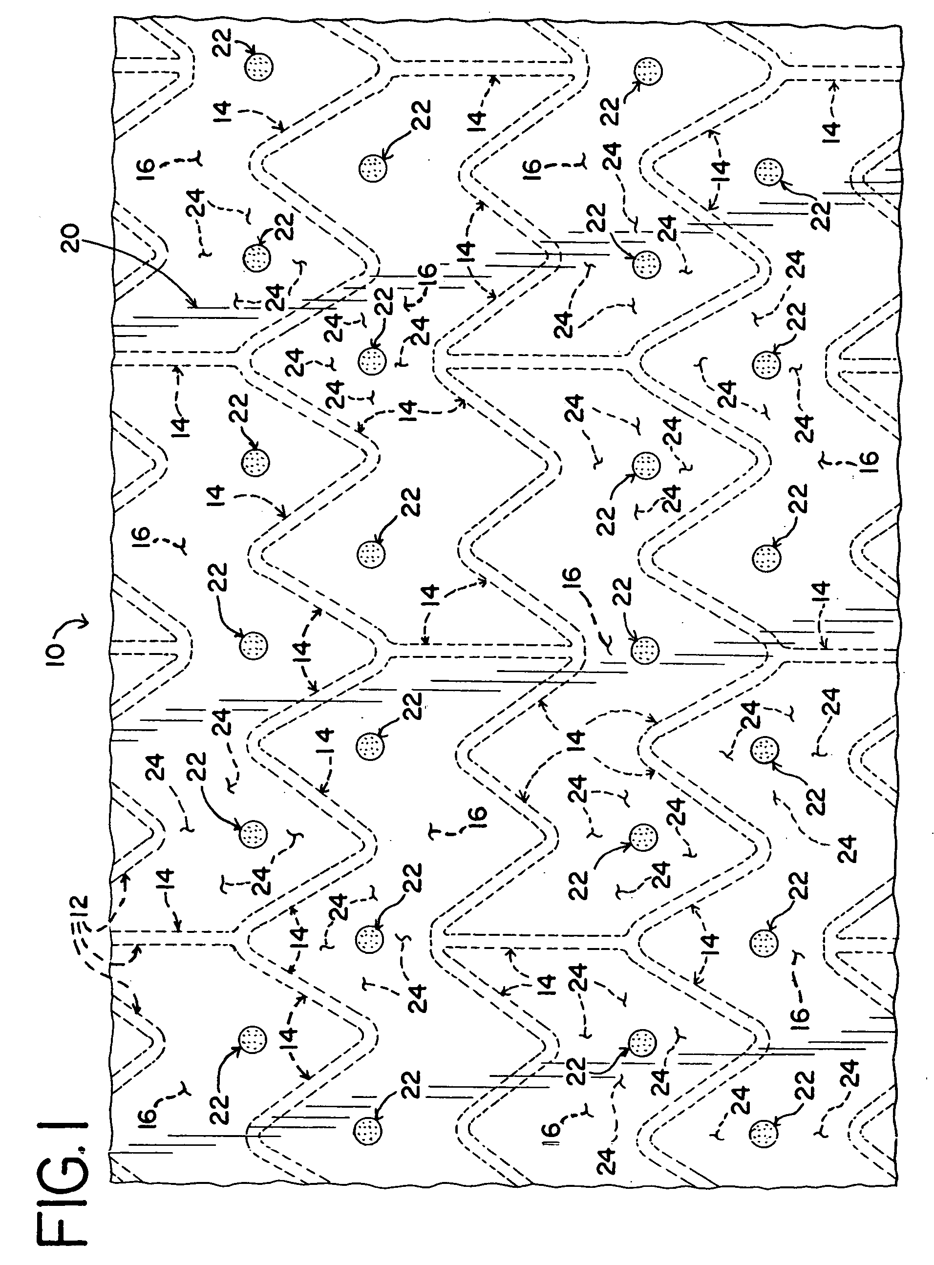
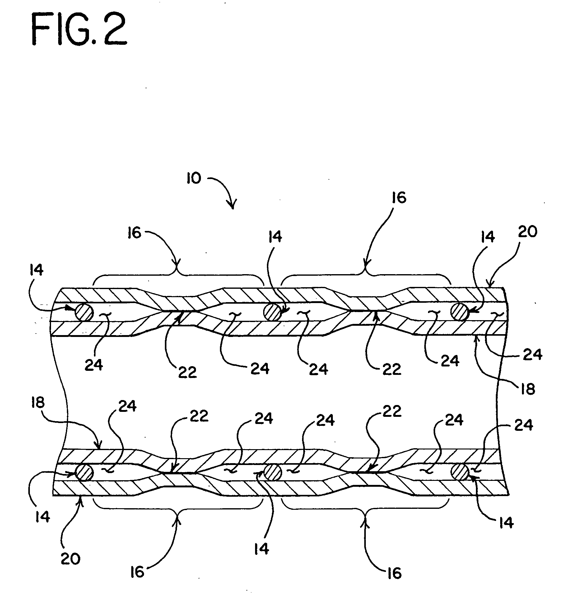
[0012] A stent-graft assembly is provided with an inner layer of graft material and an outer layer of graft material secured to a stent. The graft layers are secured to each other through openings in the stent structure. Unattached margin areas are further provided between the attached areas of the graft layers and the edges of the openings. One of the advantages of the stent-graft is that it is easier and less costly to make. Another advantage is that the stent-graft is more flexible than conventional stent-grafts. Additional details and advantages are provided below.

Problems solved by technology

If not treated, an aneurysm may eventually rupture, resulting in internal hemorrhaging.
In many cases, the internal bleeding is so massive that a patient can die within minutes of an aneurysm rupture.
However, the known conventional techniques have numerous problems associated therewith, and an improved manner of securing graft layers to a stent is desired.
This is a very labor intensive task that is time consuming and expensive, thus raising the cost of stent-grafts made by this process.
Moreover, stent-grafts made by suturing the graft layers to the stent lose much of the flexibility inherent in the stent itself.
As a result, the graft layers restrict the movement of the stent structure.
However, despite the importance of flexibility, stent-grafts that secure the graft layers directly to the stent are relatively inflexible compared to other types of stents.
However, this type of stent-graft also lacks flexibility as described above.
This causes the graft layers to restrict the movement of the stent structure.
Thus, even when the graft layers are not directly secured to the stent as described, the graft layers are still unable to move independently of the stent.

Method used


Image

  • Stent-graft with graft to graft attachment
  • Stent-graft with graft to graft attachment
  • Stent-graft with graft to graft attachment

Examples


Embodiment Construction

[0017] Referring now to the drawings, a stent-graft assembly 10 is shown. The stent-graft 10 includes a stent 12 with an inner layer 18 of graft material disposed along the luminal surface of the stent 12 and an outer layer 20 of graft material disposed along the abluminal surfaces of the stent 12. As shown in the figures, it is preferable for the graft layers 18, 20 to cover the entire luminal and abluminal surfaces. However, it is also possible for the graft layers 18, 20 to cover only a portion of the stent 12.

[0018] Various types of stents 12 may be used with the invention. For example, stents may be made from numerous metals and alloys, including stainless steel, nitinol, cobalt-chrome alloys, amorphous metals, tantalum, platinum, gold and titanium. Stents may also be made from non-metallic materials, such as thermoplastics and other polymers. The structure of the stent may also be formed in a variety of ways to provide a suitable intraluminal support structure. For example, s...


PUM


Abstract

A stent-graft assembly is provided for a variety of medical treatments. The stent-graft assembly includes a stent disposed between an inner layer of graft material and an outer layer of graft material. The graft layers are effectively secured to the stent by attaching the graft layers together through openings in the structure of the stent. Relative movement between the graft layers and the stent is made possible by providing unattached margins between the attached areas of the graft layers and the edges of the stent openings.

Description

BACKGROUND [0001] The present invention relates generally to medical devices and particularly to a stent assembly with graft layers disposed along luminal and abluminal surfaces of a stent. [0002] Although stent-graft assemblies may be used to treat a number of medical conditions, one common use of stent-graft assemblies relates to the treatment of aneurysms. As those in the art well know, an aneurysm is an abnormal widening or ballooning of a portion of an artery. Generally, this condition is caused by a weakness in the blood vessel wall. High blood pressure and atherosclerotic disease may also contribute to the formation of aneurysms. It is possible for aneurysms to form in blood vessels throughout the vasculature. However, common types of aneurysms include aortic aneurysms, cerebral aneurysms, popliteal artery aneurysms, mesenteric artery aneurysms, and splenic artery aneurysms. If not treated, an aneurysm may eventually rupture, resulting in internal hemorrhaging. In many cases,...

Claims


Application Information

Patent Timeline
Patent Type & Authority Applications(United States)
IPC IPC(8): A61F2/06
CPCA61F2/07A61F2002/072A61F2002/075A61F2/915
Inventor HUNT, JAMES B.
Owner COOK MEDICAL TECH LLC
Why Eureka
Try Eureka