Microfluidic system

a microfluidic system and microfluidic technology, applied in the direction of positive displacement liquid engines, instruments, machines/engines, etc., can solve the problems of the same change in the dielectric constant of oil, and achieve the effect of small physical size and convenient us

Inactive Publication Date: 2005-10-13
KAVLICO CORP
View PDF19 Cites 19 Cited by
  • Summary
  • Abstract
  • Description
  • Claims
  • Application Information

AI Technical Summary

Benefits of technology

[0004] Another object of the invention is to provide a viscosity measuring system which is of r...

Problems solved by technology

However, the dielectric constant of oil also changes with usage; and in some cases, th...

Method used


Image

  • Microfluidic system
  • Microfluidic system
  • Microfluidic system

Examples


Embodiment Construction

[0024] While the specification describes particular embodiments of the present invention, those of ordinary skill can devise variations of the present invention without departing from the inventive concept.

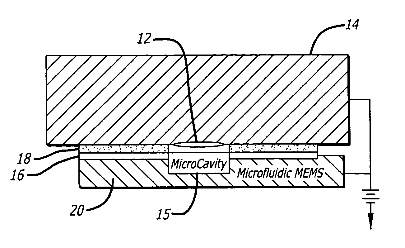
[0025] Referring more particularly to the drawings, FIG. 1 shows a semiconductor diaphragm 12 formed on a body of semi-conductive material 14. Underlying the diaphragm 12 is a microcavity 15 into which fluid is directed through the microfluidic channels 16. A thin layer of adhesive 18 bonds the upper body of semi-conductive material 14 to the lower body of semi-conductive material 20 into which the channels 16 are formed. Instead of adhesive material the semi-conductive bodies 14 and 20 may be fusion bonded, with one such method being described in U.S. Pat. No. 5,578,843.

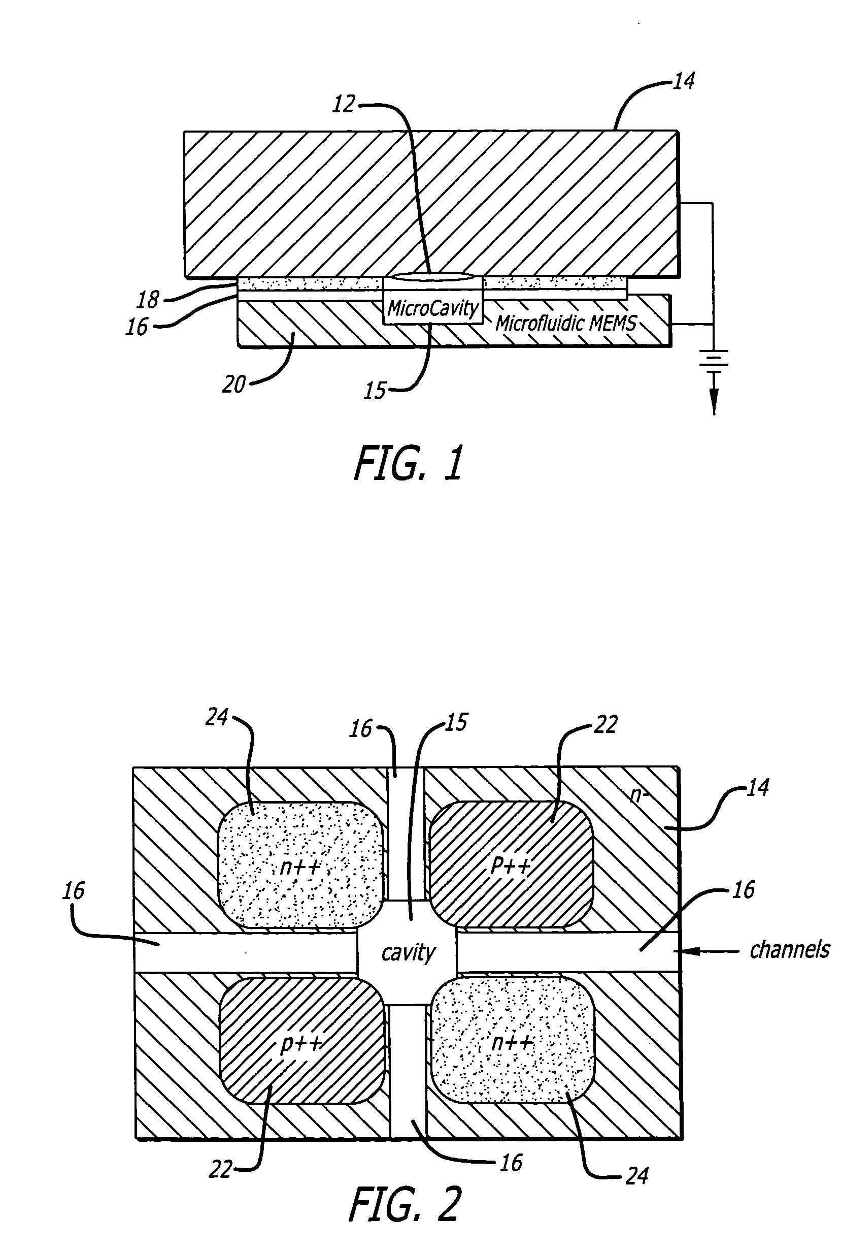
[0026]FIG. 2 is a schematic cross-sectional view through semiconductive body 14 near the lower surface thereof, showing the electrode zones 24 where the silicon body is heavily doped with arsenic, phosphorous or...


PUM


Abstract

A system for measuring viscosity includes microfluidic passageways coupled to a micro-cavity, and semiconductive electrodes for applying an electric field across said electrodes. The resultant pressure increase and deflection of the diaphragm changes the capacitance of the MEMS capacitor. Pumps such as a thermal pump or a surface acoustic wave pump control flow of fluid to be measured to and from the micro-cavity. Semiconductor device fabrication techniques are employed to produce the viscosity measurement system.

Description

FIELD OF THE INVENTION [0001] This invention relates to the measurement of viscosity of polarizable dielectric fluids and related microfluidic systems. BACKGROUND OF THE INVENTION [0002] For the determination of the contamination of a fluid, such the oil in an internal combustion engine, for example, it has previously been proposed to measure the dielectric constant of the oil. In the event of contamination by coolant, water, or gasoline, a measurable change in dielectric constant may be observed. However, the dielectric constant of oil also changes with usage; and in some cases, the dielectric constant measurement does not uniquely identify the source of the contamination. SUMMARY OF THE INVENTION [0003] Accordingly, one object of the present invention is to provide additional information regarding the properties of the fluid, to identify the nature of any contamination of the fluid, for example. [0004] Another object of the invention is to provide a viscosity measuring system whic...

Claims


Application Information

Patent Timeline
IPC IPC(8): F04B19/24G01N11/08G01N11/00F04B43/06F04B43/04
CPCF04B19/24F04B43/043F04B43/06G01N11/08
Inventor SPIVAK, ALEXANDER F.
Owner KAVLICO CORP
Why Eureka
Try Eureka