Eureka AIR delivers breakthrough ideas for toughest innovation challenges, trusted by R&D personnel around the world.

Thermostat monitoring system of vehicle and method thereof

a technology of thermostat and monitoring system, which is applied in the direction of machines/engines, electric control, instruments, etc., can solve the problems of deteriorating exhaust emission characteristics, slow increase of actual coolant temperature, and inability to normally control the amount of coolant flowing between the engine and the radiator, etc., to achieve the effect of increasing stability and credibility of monitoring

Inactive Publication Date: 2005-10-13
HYUNDAI MOTOR CO LTD
View PDF1 Cites 17 Cited by
  • Summary
  • Abstract
  • Description
  • Claims
  • Application Information

AI Technical Summary

Benefits of technology

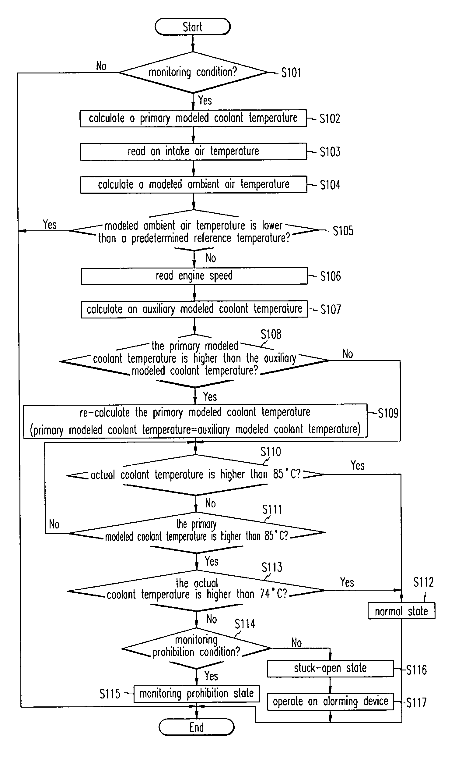
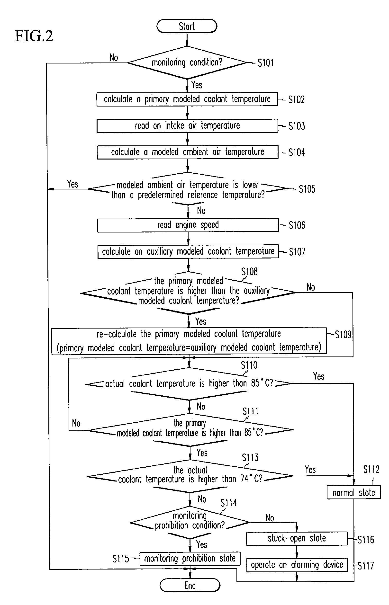
[0013] Embodiments of the present invention provide a thermostat monitoring system and method that use a primary coolant temperature modeling method and an auxiliary coolant temperature modeling method, and thereby increase stability and credibility of monitoring a stuck-open state of a thermostat.

Problems solved by technology

If the thermostat is stuck in an open state, control of the amount of coolant flowing between the engine and the radiator cannot be normally performed.
Therefore, the warm-up period for the engine becomes longer when compared to a normal state, so exhaust emission characteristics become deteriorated.
However, even if the thermostat operates normally, the actual coolant temperature rises very slowly in a cold area because the ambient air temperature is low.
In such cases, even when the thermostats operate normally, it may be erroneously determined that the thermostat is in a stuck-open state.
Thus, in the thermostat monitoring method according to the prior art as stated above, it can be erroneously determined that the normally operated thermostat is in the stuck-open state when a vehicle is driven in a very cold area or in a low load state.
However, regulations for monitoring times in the OBD-2 cannot be met.

Method used


Image

  • Thermostat monitoring system of vehicle and method thereof
  • Thermostat monitoring system of vehicle and method thereof
  • Thermostat monitoring system of vehicle and method thereof

Examples


Embodiment Construction

[0032] Hereinafter, a preferred embodiment of the present invention will be described in detail with reference to the accompanying drawings.

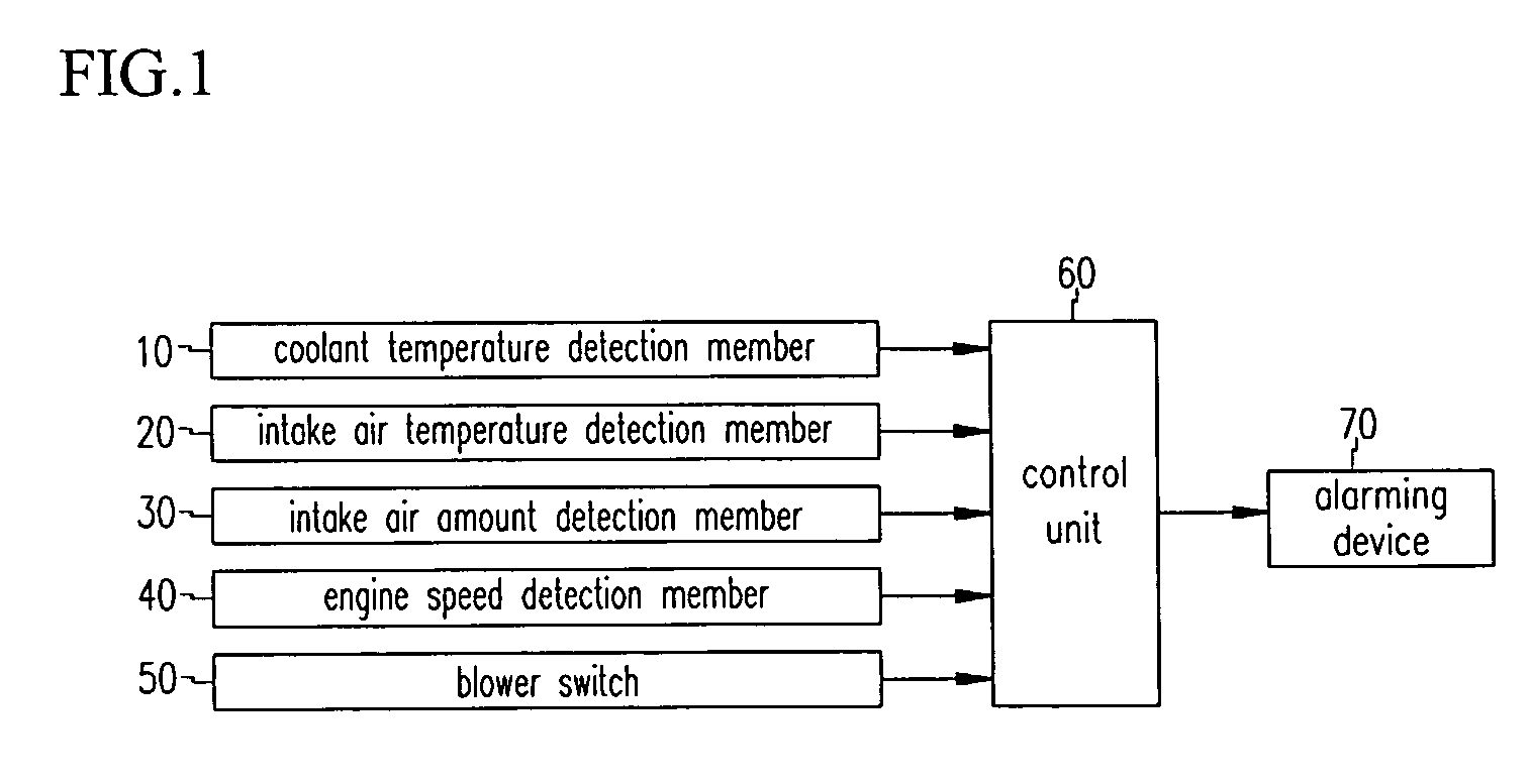
[0033] Referring to FIG. 1, a thermostat monitoring system according to an embodiment of the present invention comprises a coolant temperature detection member 10, an intake air temperature detection member 20, an intake air amount detection member 30, an engine speed detection member 40, a blower switch 50, and a control unit 60. The thermostat monitoring system may further comprise an alarm device 70, which can be an a lamp or a buzzer. Control unit 60 may comprise a processor and associated hardware and software as may be selected and programmed by a person of ordinary skill in the art based on the teachings contained herein.

[0034] The coolant temperature detection member 10 detects a temperature of coolant and outputs a corresponding electrical signal. The intake air temperature detection member 20 detects the temperature of intake air int...


PUM


Abstract

A thermostat monitoring system is provided which comprises a coolant temperature detection member for detecting a temperature of a coolant. An intake air temperature detection member detects a temperature of ambient air introduced into combustion chambers. An intake air amount detection member detects an amount of intake air. An engine speed detection member detects an engine speed; a blower switch detects a selected contacting point for driving a blower motor; and a control unit calculates a primary modeled coolant temperature and an auxiliary modeled coolant temperature based on information detected by the coolant temperature detection member, the intake air temperature detection member, the intake air amount detection member, the engine speed detection member, and the blower switch, and for monitoring using the primary modeled coolant temperature and the auxiliary modeled coolant temperature to determine whether a thermostat is in a stuck-open state.

Description

CROSS REFERENCE TO RELATED APPLICATIONS [0001] This application claims priority of Korean Application No. 10-2004-0024129, filed on Apr. 8, 2004, the disclosure of which is incorporated herein by reference. TECHNICAL FIELD OF THE INVENTION [0002] The present invention relates to a system and a method for monitoring a thermostat of a vehicle. BACKGROUND OF THE INVENTION [0003] Generally, a thermostat is installed between an engine and a radiator, and it is automatically opened or closed in response to a change of a coolant temperature such that an amount of coolant flowing to the radiator is regulated, and thereby a temperature of the engine is maintained to be constant so that overheating or overcooling of the engine can be prevented. Therefore, the engine may operate at its highest performance level. In addition, the thermostat increases efficiency of heating an inner space of a vehicle, prevents consumption of coolant, and maintains the temperature of the coolant. [0004] Generally...

Claims


Application Information

Patent Timeline
IPC IPC(8): F02D41/22F02D41/18F01P7/16F02D45/00F01P11/16F01P5/14G01M99/00F01P7/14F01P3/20
CPCF01P5/14F01P11/16F01P2023/00F01P2023/08F01P2025/13F01P2025/60F01P2025/62F01P2025/64F01P2031/00F01P2031/20F02D41/18F02D41/22F02D2041/1433Y02T10/40B44C5/0469B44F9/02
Inventor KIM, HYUNG KEE
Owner HYUNDAI MOTOR CO LTD
Why Eureka
Eureka Blog
Learn More