Stable metal structure with tungsten plug

Active Publication Date: 2005-10-13
TAIWAN SEMICON MFG CO LTD
View PDF8 Cites 30 Cited by
  • Summary
  • Abstract
  • Description
  • Claims
  • Application Information

AI Technical Summary

Benefits of technology

[0013] The electrical conductive region 4 may also include a silicide formed at the top of the source/drain or a gate poly. Silicide improves the contact between the underlying region and the metal contact plug that is formed in subsequent steps. It should also be appreciated that region 4 may be formed of many materials that are used in IC fabrication. For example, region 4 may be a metal line or a composite metal

Problems solved by technology

The parasitic capacitance associated with these metal interconnections has become a major factor that limits the circuit speed of such high performance ICs.
However, the relatively high-k value of the regular-k dielectrics results in high parasitic capacitance.
However, low-k materials cannot be used as the first level dielectric since their physical and chemical properties are si

Method used


Image

  • Stable metal structure with tungsten plug
  • Stable metal structure with tungsten plug
  • Stable metal structure with tungsten plug

Examples


Example

[0011] The making and using of the presently preferred embodiments are discussed in detail below. It should be appreciated, however, that the present invention provides many applicable inventive concepts that can be embodied in a wide variety of specific contexts. The specific embodiments discussed are merely illustrative of specific ways to make and use the invention, and do not limit the scope of the invention.

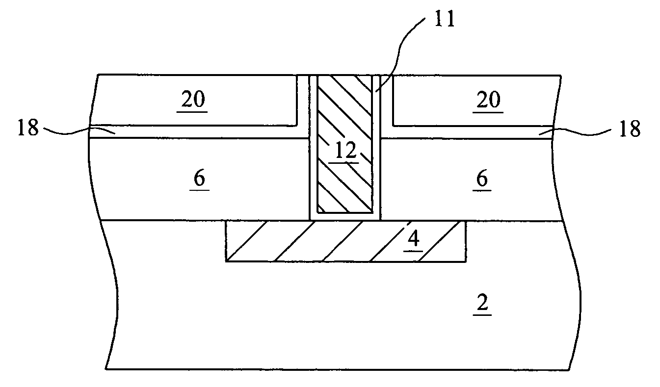
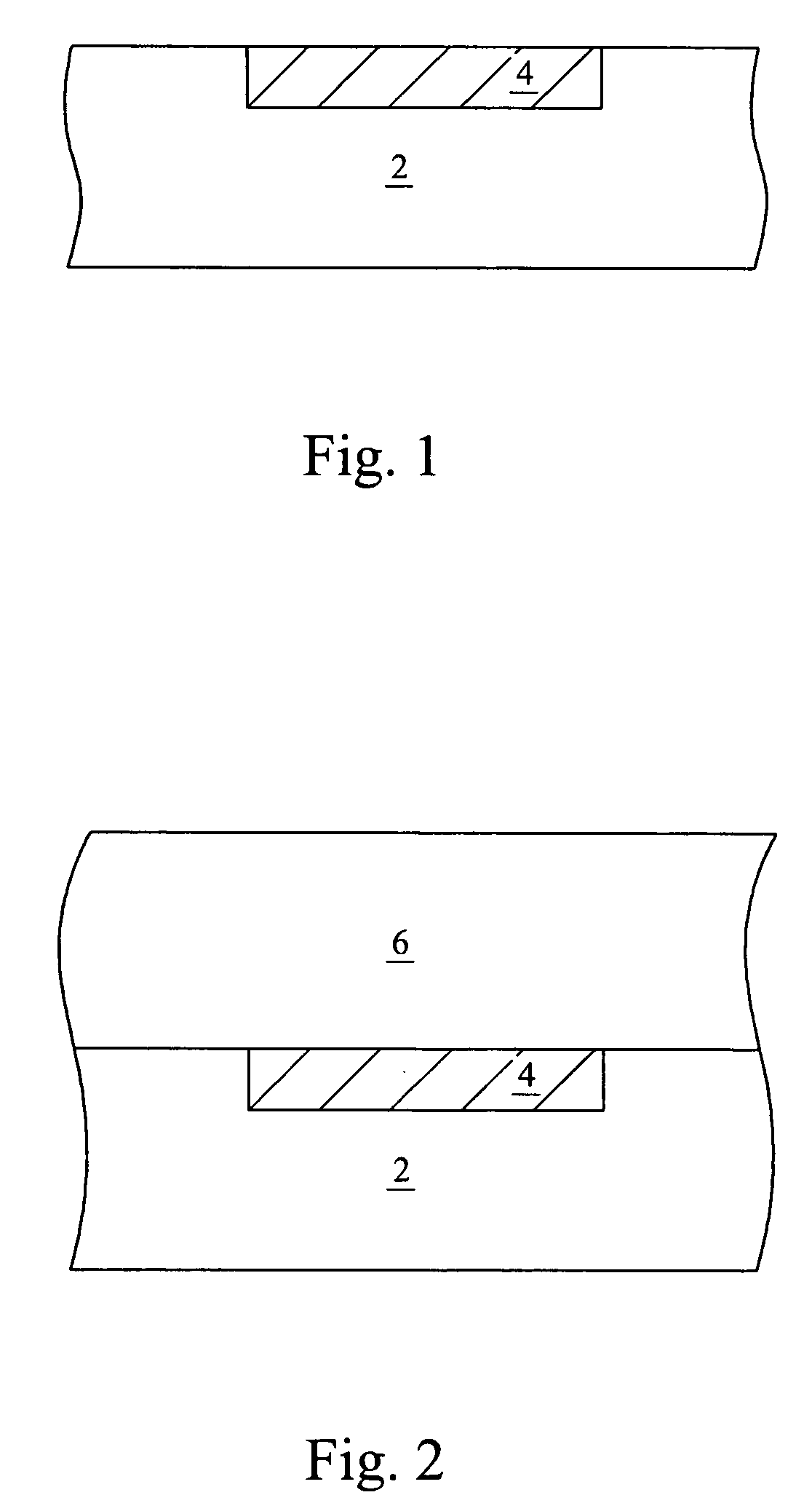
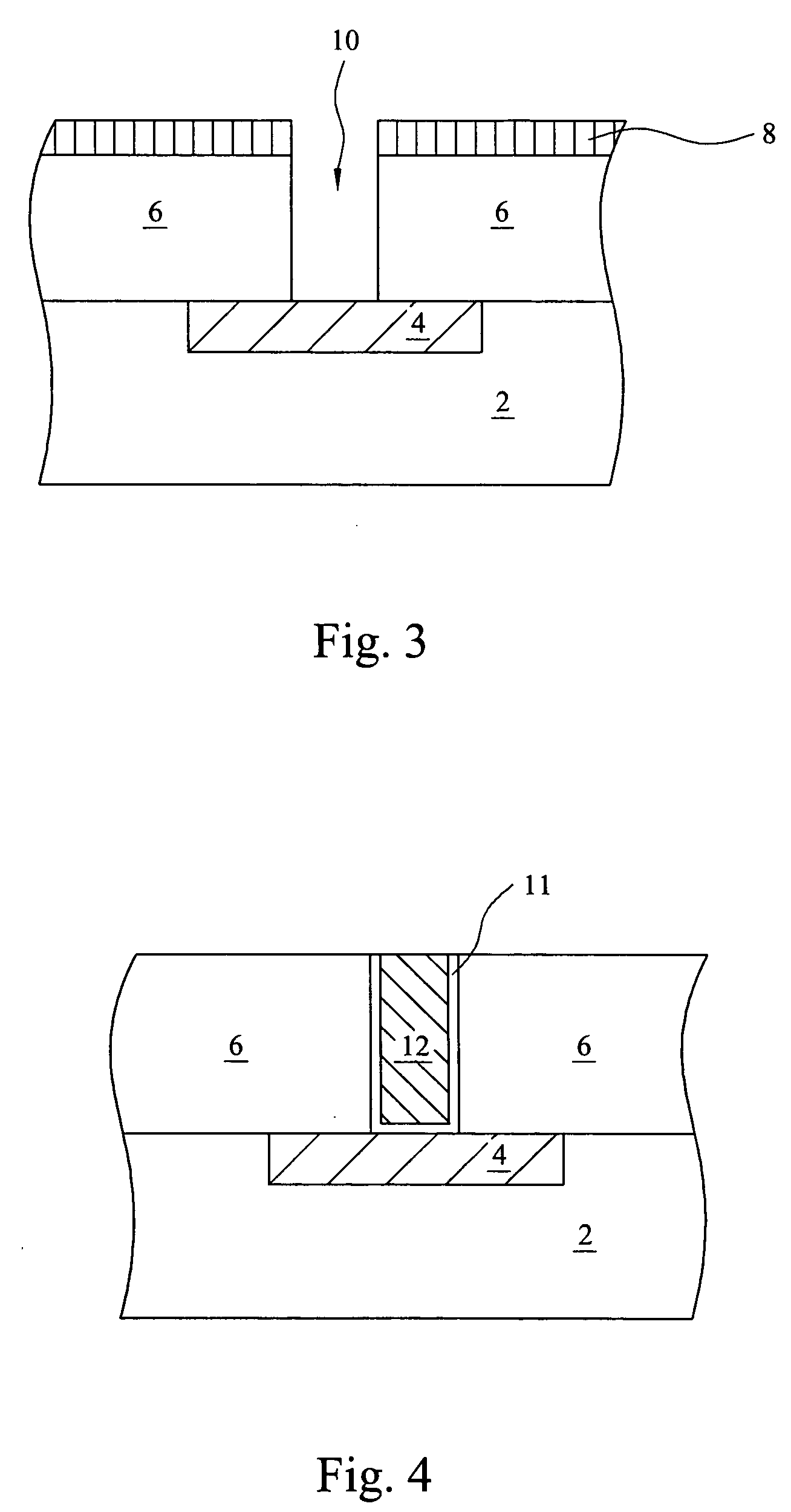
[0012]FIGS. 1 through 10 illustrate preferred embodiments of the present invention. FIG. 1 illustrates an electrical conductive region 4 and a substrate 2. In a preferred embodiment, electrical conductive region 4 is a source / drain formed of materials that are epitaxially grown in recesses formed in substrate 2. In another embodiment, region 4 is a source / drain epitaxially deposited on substrate 2 using know epitaxy techniques. In yet other embodiments, electrical conductive region 4 is a gate structure (not shown) where a gate electrode is formed on substrate 2.

[0013] The...


PUM


Abstract

In the preferred embodiment, a thick regular-k dielectric is formed on a substrate. A tungsten plug is formed in the thick regular-k dielectric. The thick regular-k dielectric is recessed and a thin low-k dielectric is formed on the thick regular-k dielectric. The thin low-k dielectric acts as a glue layer and as an etch stop layer. A thick low-k dielectric is formed on the thin low-k material. Optionally, an opening is formed through the thick low-k dielectric to expose the tungsten plug. The opening is then filled with copper or copper alloys.

Description

[0001] This application claims priority to Provisional Application Ser. No. 60 / 559,857, filed on Apr. 6, 2004, and entitled “Stable Metal Structure with Tungsten Plug”, which application is hereby incorporated herein by reference.TECHNICAL FIELD [0002] This invention relates generally to integrated circuit structures, and more specifically to inter level dielectrics. BACKGROUND [0003] As integrated circuit scaling proceeds into the deep sub-micron regime, the number of transistors on high performance, high density ICs is in the tens of millions, in accordance with the historical trend of Moore's Law. This has necessitated that such ICs feature multiple layers of high-density metal interconnects, and that the layers be separated by inter level dielectrics (ILD), also sometimes known as inter-metal dielectrics (IMD). The parasitic capacitance associated with these metal interconnections has become a major factor that limits the circuit speed of such high performance ICs. A conventiona...

Claims


Application Information

Patent Timeline
IPC IPC(8): H01L21/28H01L21/4763H01L21/768H01L23/485H01L23/52H01L23/522H01L23/528H01L23/532
CPCH01L21/76801H01L21/76834H01L21/76835H01L21/76852H01L21/76885H01L23/485H01L23/5226H01L23/5283H01L23/53238H01L23/53295H01L2924/3011H01L2924/0002H01L2924/00
Inventor TSENG, HORNG-HUEIJANG, SYUN-MING
Owner TAIWAN SEMICON MFG CO LTD
Why Eureka
Try Eureka