Variable reluctance motor

a variable reluctance and motor technology, applied in the field of motors, can solve the problems of increasing the size of the magnet required for a given output force, and achieve the effect of improving the efficacy and operational characteristics of variable reluctance motors

Active Publication Date: 2005-10-13
COCHLEAR LIMITED
View PDF5 Cites 7 Cited by
  • Summary
  • Abstract
  • Description
  • Claims
  • Application Information

AI Technical Summary

Benefits of technology

[0007] In view of the foregoing, a primary object of the present invention is to improve the operational characteristics of variable reluctance motors. Another object of the present invention is to improve the efficacy of variable reluctance motors, e.g. force generated for a given input current or motor size. Another object of the present invention is to provide a variable reluctance motor having an output force that is linearly related to an input current.
[0013] In either case, e.g. whether a permanent magnet or electromagnetic member is utilized, it is desirable that biasing force generated by the magnetic member be larger than the electromagnetic field generated by the drive coil of the motor. It is also desirable, but not necessary, that the magnetic member be located in the motor so that it is substantially outside of the path traveled by the electromagnetic fields generated by the drive coil of the motor. The present inventors have recognized that this in turn results in a greater motor efficacy through reduced reluctance, e.g. output force for a given input current.
[0015] Advantageously, the biasing force from the magnetic member operates to cancel non-linearities in the motor to provide a linear relationship between the input current to the drive coil and an output force of the motor. Also, advantageously, the biasing force applied by the magnetic member does not affect the acoustic performance of the motor. Still yet another advantage provided where the magnetic member is located outside of the path traveled by the electromagnetic field generated by the drive coil, is that reluctance in the motor is reduced thereby increasing the motor efficacy, e.g. output force for a given input current.
[0017] In another feature of the present aspect, the motor is configured to define a path of travel for the electromagnetic field emitted from the drive coil, which is substantially continuously magnetically conductive. For instance, the motor may include a back iron portion designed to minimize air gaps in the path traveled by the electromagnetic field from the drive coil to reduce reluctance and increase motor efficacy e.g. output force for a given input current.
[0020] In another feature of the present aspect, the armature and the stator of the present motor may each include a biocompatible enclosure. According to this characterization, the driver may be separately sealed within the transducer body such that sealing is not required at the movable connection between the actuator and the transducer body. That is, the independent driver enclosure(s) eliminates the necessity of providing an interconnection between the actuator and the transducer body that is both sealed and movable.

Problems solved by technology

Unfortunately, however, in this design, flux from the magnetic field passing through the conductor increases the reluctance, e.g. the magnetomotive force across a structure divided by the flux through the area of the structure, of the magnetic path thereby increasing the size of the magnet required for a given output force.

Method used


Image

  • Variable reluctance motor
  • Variable reluctance motor
  • Variable reluctance motor

Examples


Embodiment Construction

[0030] Reference will now be made to the accompanying drawings, which at least assist in illustrating the various pertinent features of the present invention. In this regard, the following description is presented for purposes of illustration and description and is not intended to limit the invention to the form disclosed herein. Consequently, variations and modifications commensurate with the following teachings, and skill and knowledge of the relevant art, are within the scope of the present invention. The embodiments described herein are further intended to enable others skilled in the art to utilize the invention in such, or other embodiments, and with various modifications required by the particular application(s) or use(s) of the present invention.

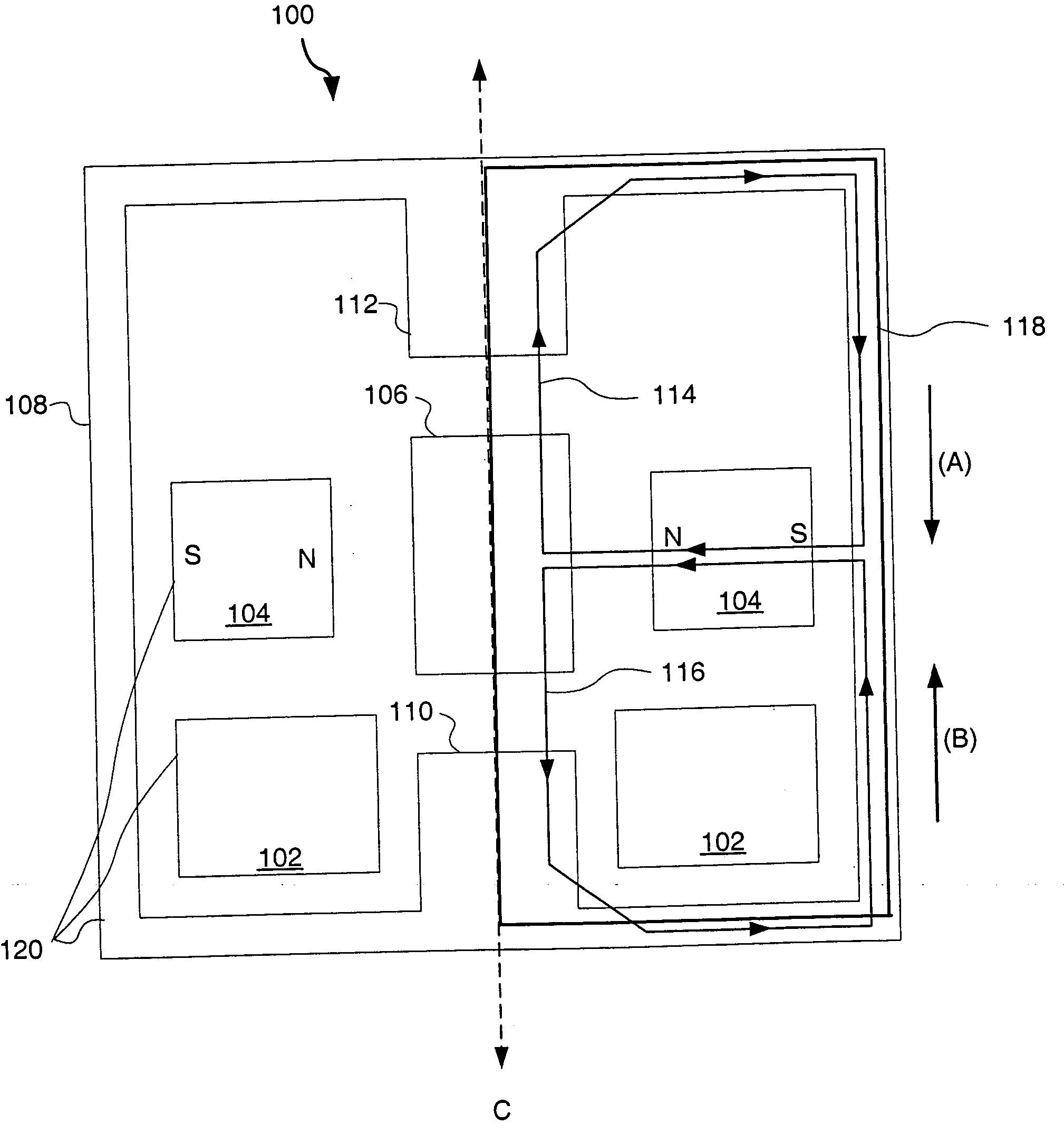
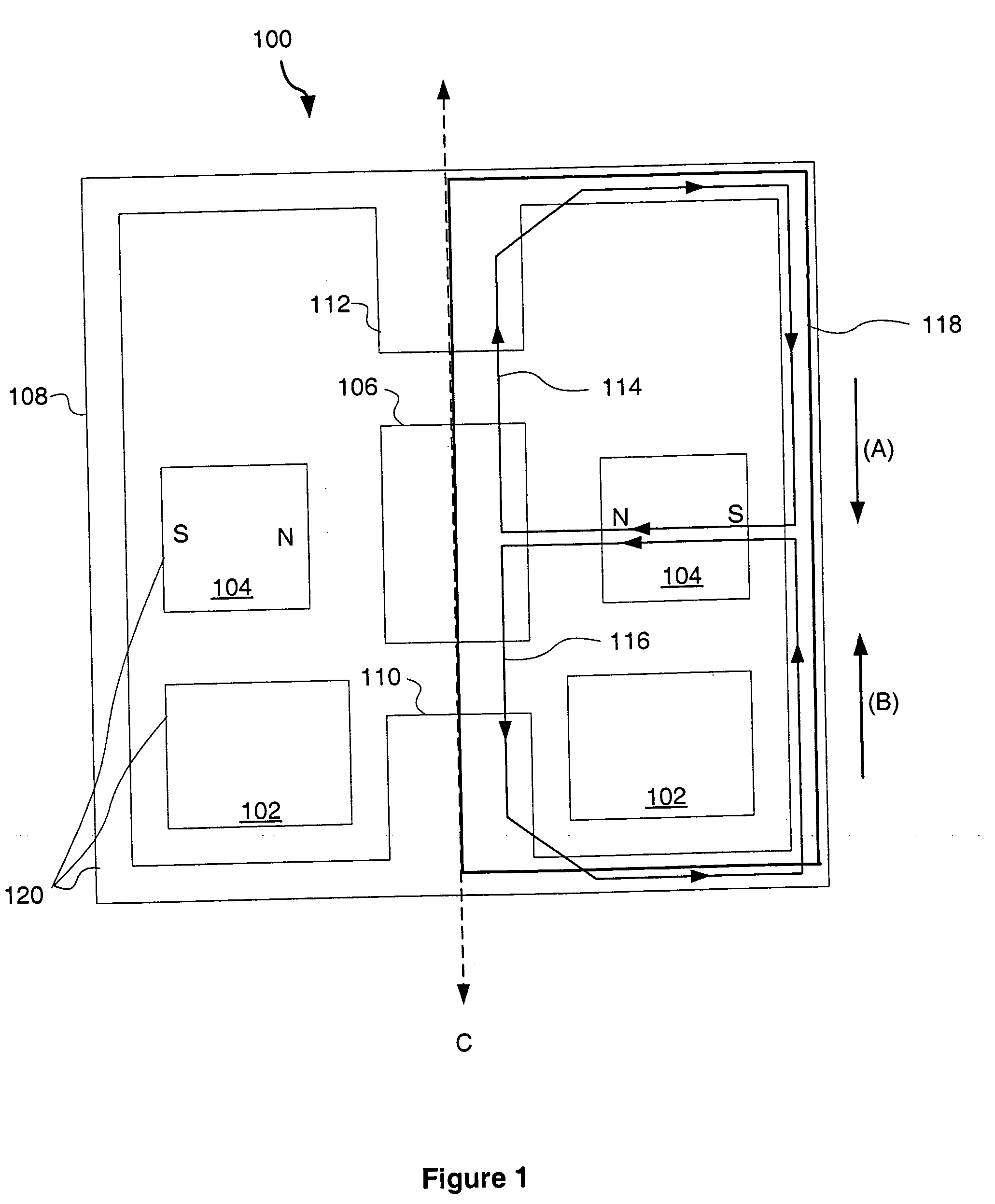
[0031]FIG. 1 illustrates one example of a variable reluctance motor according to the present invention, namely motor 100. The motor 100 includes an armature 106 and a stator 120; including at least one drive coil 102, at least one m...


PUM


Abstract

A variable reluctance motor is provided having a linear relationship between an input current and an output force. According to one aspect of the invention, the motor comprises a stator, an armature, and at least one magnetic member to provide a biasing force on the armature. According to this characterization, the motor also includes a drive coil to generate an electromagnetic field in response to a current input. The electromagnetic field, in turn, moves the armature relative to the stator during motor operation.

Description

FIELD OF THE INVENTION [0001] The present invention relates to motors, and in particular, to a variable reluctance motor having a substantially linear relationship between input current and a resulting force. BACKGROUND OF THE INVENTION [0002] Electromagnetic motors are utilized in a variety of applications, both as motors to deliver force and as sensors to detect force acting on the motor. Electromagnetic motors employ one or more coils and one or more magnets that comprise an armature (moving portion of the motor) and a stator (stationary portion of the motor) to generate an output force. One type of electromagnetic motor, sometimes referred to in the art as a Lorentz motor, operates on the principle that force is created by the interaction of magnetic fields. In this case, a current is provided to a conductor, such as a coil, located in a magnetic field provided by a magnet, to generate a force that is proportional to the input current. In other words, a linear relationship exist...

Claims


Application Information

Patent Timeline
Patent Type & Authority Applications(United States)
IPC IPC(8): H02K41/00H02K19/20H02K19/06H02K33/02
CPCH02K19/06H02K33/02
Inventor SCHNEIDER, ROBERT EDWINMILLER, SCOTT ALLAN III
Owner COCHLEAR LIMITED
Why Eureka
Try Eureka