Leakage monitoring system

a leakage monitoring and leakage detection technology, applied in the direction of instruments, emergency protective arrangements for limiting excess voltage/current, switch operated by current/voltage unbalance, etc., can solve the problems of difficult to output a timely alarm, difficult to maintain continuous monitoring, and sometimes overlooked symptoms of abnormalities, etc., to achieve easy calibration, preventive maintenance, and eliminate the effect of trouble after installation

Inactive Publication Date: 2005-10-13
HITACHI IND EQUIP SYST CO LTD
View PDF4 Cites 86 Cited by
  • Summary
  • Abstract
  • Description
  • Claims
  • Application Information

AI Technical Summary

Benefits of technology

[0048] Further, according to the present invention, by a monitoring device connected to the secondary winding of the zero-phase current transformer built in the circuit breaker, it is possible to measure changes in leakage current, grasp the insulation condition of the load circuit, and predict insulation deterioration, and by using a calibration button contained in the circuit breaker, determine whether the monitoring device makes measurements correctly. Even if a secular change has occurred in the parts in the monitoring device, it is easy to perform calibration. Moreover, it is easy to inspect a distribution board or a switchboard before shipment, so that trouble after installation at the site can be eliminated. By communication between the monitoring device and the host system, calibration records can be stored, and preventive maintenance and management with high reliability can be realized.
[0049] According to the present invention, an insulation monitoring system can be established without increasing the installation space and wiring man-hours for the zero-phase current transformer, and the present invention can be applied securely to the existing circuits.
[0050] According to the present invention, it is possible to monitor the deterioration of the circuit breaker.
[0051] According to the present invention, with a single insulation monitoring device, it is possible to implement insulation monitoring for multiple banks and multiple circuits, and an economical monitoring system can be established.
[0052] Further, according to the present invention, constant leakage monitoring and recording can be performed by the monitoring device, and a leakage trip can be set in the circuit breaker at low cost; consequently, it is possible to provide a system which integrates monitoring, recording and control.
[0053] Further, according to the present invention, because the insulation condition can be monitored without applying a voltage, the salient effect is that there is no need to provide a device for applying a voltage.

Problems solved by technology

In this case, continuous monitoring is hard to keep up, with the result that symptoms of abnormality are sometimes overlooked.
With the monitoring device which detects temperature by a temperature sensor externally attached to the circuit breaker and outputs an alarm when abnormal heat is generated, temperature monitoring is carried out by measuring absolute temperatures, there is a problem that at the time of abnormal heat generation, the device does not pay attention to the magnitude of a load current in temperature management, and therefore it is difficult to output a timely alarm.

Method used


Image

  • Leakage monitoring system
  • Leakage monitoring system
  • Leakage monitoring system

Examples


embodiment 1

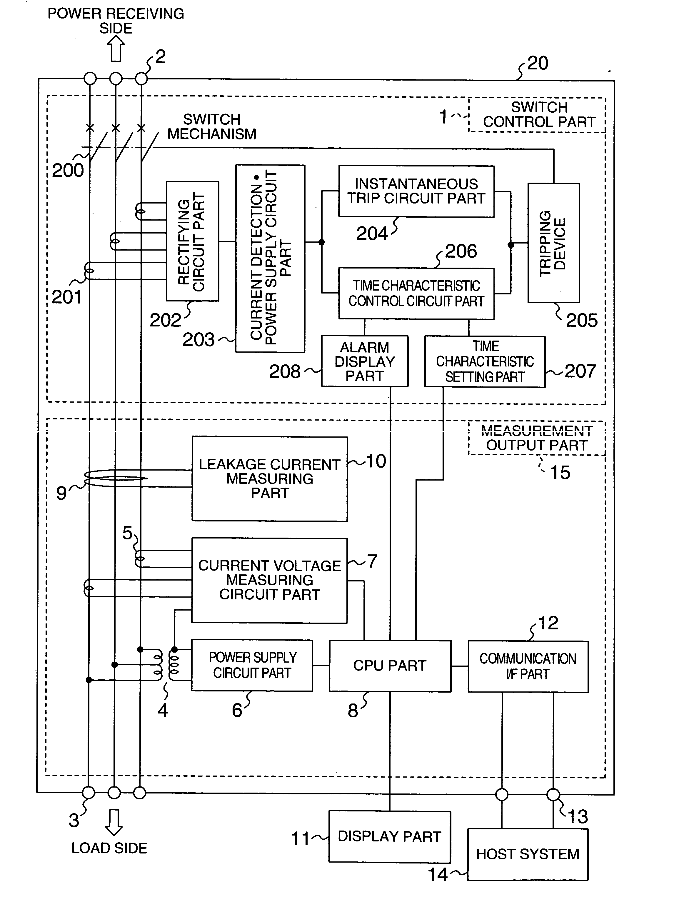
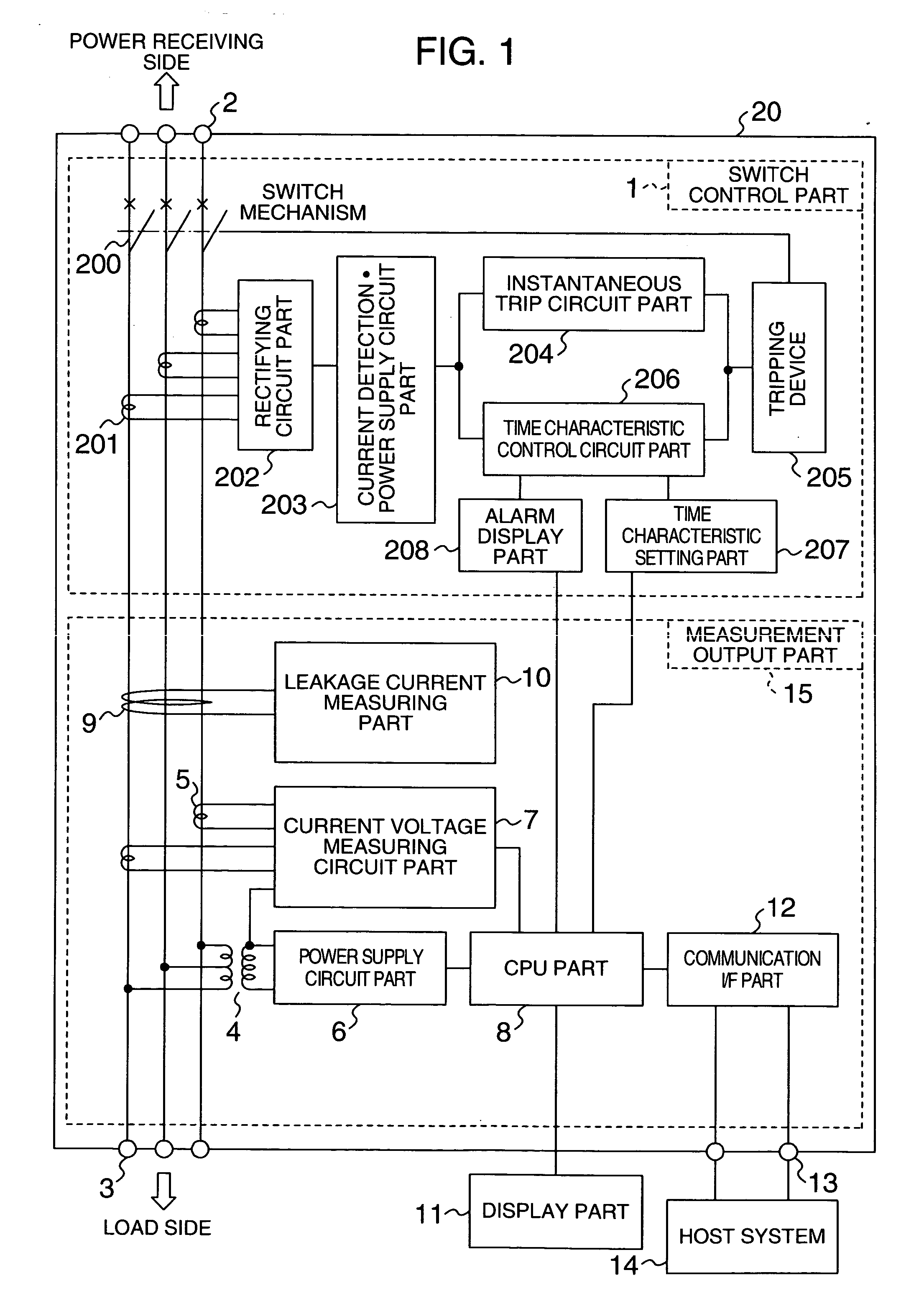
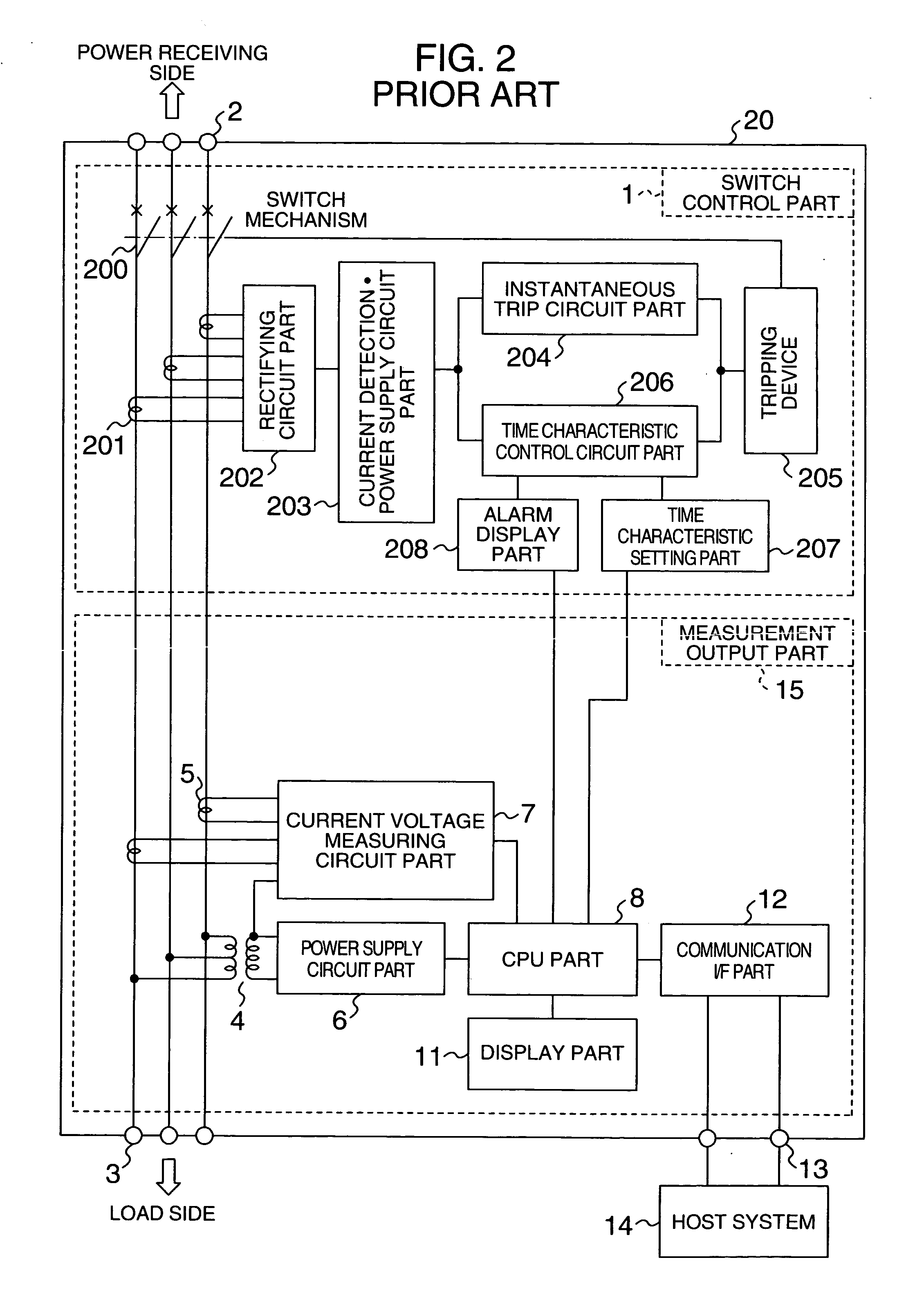
[0080]FIG. 1 shows an embodiment according to claims 1 to 6, and FIG. 2 is a block diagram showing a circuit breaker with a measuring function of prior art.

[0081] In FIGS. 1 and 2, the number 20 denotes a circuit breaker, 1 denotes a switch controller, 2 denotes a power-receiving-side terminal block, 3 denotes a load-side terminal block, 4 denotes a transformer for measurement, 5 denotes a current transformer for measurement, 7 denotes a current / voltage measuring circuit part, 8 denotes a CPU part, 11 denotes a display part, 12 denotes a communication I / F part, 13 denotes a communication terminal block, 14 denotes a host system, 15 denotes a measurement output part, 200 denotes a switching mechanical part, 201 denotes a current transformer for control, 202 denotes a rectifying circuit part, a 203 denotes a current detection power circuit part, 204 denotes an instantaneous-trip circuit part, 205 denotes a tripping device, 206 denotes time characteristic control circuit part, 207 den...

embodiment 2

[0084]FIG. 4 shows the structure of the circuit breaker and a leakage monitoring terminal block according to claims 7 to 10 of the present invention. In FIG. 4, 21 denotes a circuit breaker, 22 denotes terminals connected to the power supply side, 23 denotes switch contacts, and 24 denotes bimetal elements to detect overcurrent and make the contacts 23 open when the load current is larger than a predetermined value. The number 25 denotes main conductors connecting the terminals 22 to terminals 26 on the load side, and the conductors 25 are arranged passing through a zero-phase current transformer 27, which will be described later. FIG. 4 shows the three main conductors passing through the zero-phase current transformer 27 to show a three-phase three-wire or single-phase three-wire circuit breaker. The number 27 denotes a zero-phase current transformer which includes a secondary winding 271 and a tertiary winding 272, and the secondary winding 271 is drawn out and connected to a term...

embodiment 3

[0086]FIG. 6 shows a leakage monitoring system including the circuit breaker and the leakage monitoring device. The number 33 denotes a transformer, and 34 denotes a power distribution board, which includes a plurality of circuit breakers 21 described above. The number 36 denotes a leakage monitoring device for multiple circuits based on the above-mentioned leakage monitoring device 32 and adapted to monitor a plurality of circuit breakers 21 by increasing the number of inputs. This leakage device is added with a communication function. The number 37 denotes communication media, and 38 denotes a host system, such as a personal computer. The number 28 denotes calibration buttons arranged to be operated on the front faces of the circuit breakers 21. Each circuit breaker 21 is connected to the leakage monitoring device 36 for multiple circuits. In the system configured as described, in the real operating state, electric power is supplied from the transformer 33 to the load equipment 35...


PUM


Abstract

The system makes it possible to monitor various electrical variables by using a simple structure at low cost with ease and with high reliability by a circuit breaker which jointly includes a current transformer to detect current, a transformer to detect voltage, and a zero-phase current transformer to detect leakage current, in addition to the switch controller to perform the basic function of the circuit breaker. Moreover, the system also provides a function to display various measured values, obtained as described above, by a display unit that can be detached and installed separately from the measuring section to display data sent in digital form by data transmission.

Description

BACKGROUND OF THE INVENTION [0001] The present invention relates to technology for monitoring the state of a circuit breaker, and more particularly to technology by providing a zero-phase current transformer in the circuit breaker, measuring an leakage current of the active current included in the secondary output current, performing arithmetic operations in the circuit breaker, and transmitting data in digital form to a host system or to subordinate equipment. [0002] Further, the present invention also is concerned with technology for checking if a monitoring device itself operating normally during leakage current measurement by the monitoring device connected to the circuit breaker including a zero-phase current transformer. [0003] Further, the present invention is concerned with an insulation monitoring system to keep track of the state of the insulation. [0004] Further, the present invention relates to a device for monitoring the circuit-breaker's inside-temperature, leakage cur...

Claims


Application Information

Patent Timeline
Patent Type & Authority Applications(United States)
IPC IPC(8): G01R31/327G01R31/02H01H83/14H02H3/00H02H3/04H02H3/33H02H3/347H02H5/04
CPCH01H83/144H01H2011/0068H02H5/04H02H3/33H02H3/042
Inventor YOSHIZAKI, AKIOTAKAKAMO, NAOHIROGOTOU, SATOKOHAYAKAWA, HIDEKIWATANABE, TETSUNORISHIBUYA, HARUKI
Owner HITACHI IND EQUIP SYST CO LTD
Why Eureka
Try Eureka