Micro scale flow through sorbent plate collection device

a micro-scale flow and collection device technology, applied in the field of analyte collection, can solve the problems of compromising the dynamic range, requiring higher power consumption, and requiring high pressure drop associated with this sort of device, and achieving the effect of reducing the cost of analyte collection

Inactive Publication Date: 2005-10-13
NAVY U S A AS REPRESENTED BY THE SEC OF THE THE +1
View PDF5 Cites 45 Cited by
  • Summary
  • Abstract
  • Description
  • Claims
  • Application Information

AI Technical Summary

Problems solved by technology

Constructing a portable field instrument for the collection, storage, concentration, and possibly on-site analyte analysis, also presents challenges.
The pressure drop associated with this sort of device is typically too high for high flow applications and requires higher power consumption.
If the amount of adsorbent is minimized to allow higher flows or faster desorption, the dynamic range is compromised.
However, the inventors have recognized drawbacks in the known prior devices.
One limitation of known prior devices is the reliance upon a flow arrangement where fluid flow during collection is generally passed over the sorbent in a direction generally parallel to its surface.
Increasing contact between the analyte fluid flow and the sorbent in the collection area would require creating a turbulent flow, a difficult task given the practical requirements including, for example, constraints such as a limitation on the amount of pressure drop.

Method used


Image

  • Micro scale flow through sorbent plate collection device
  • Micro scale flow through sorbent plate collection device
  • Micro scale flow through sorbent plate collection device

Examples


Embodiment Construction

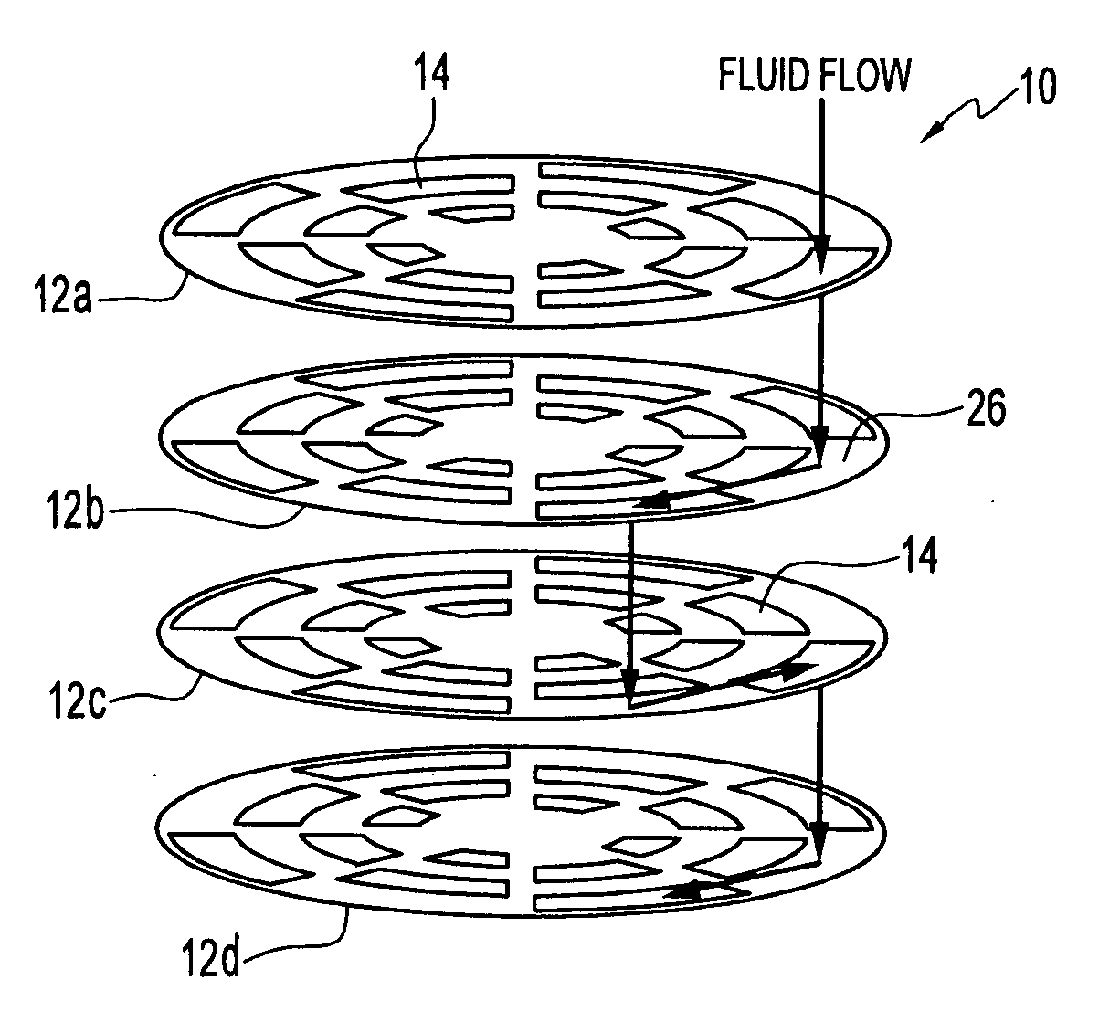
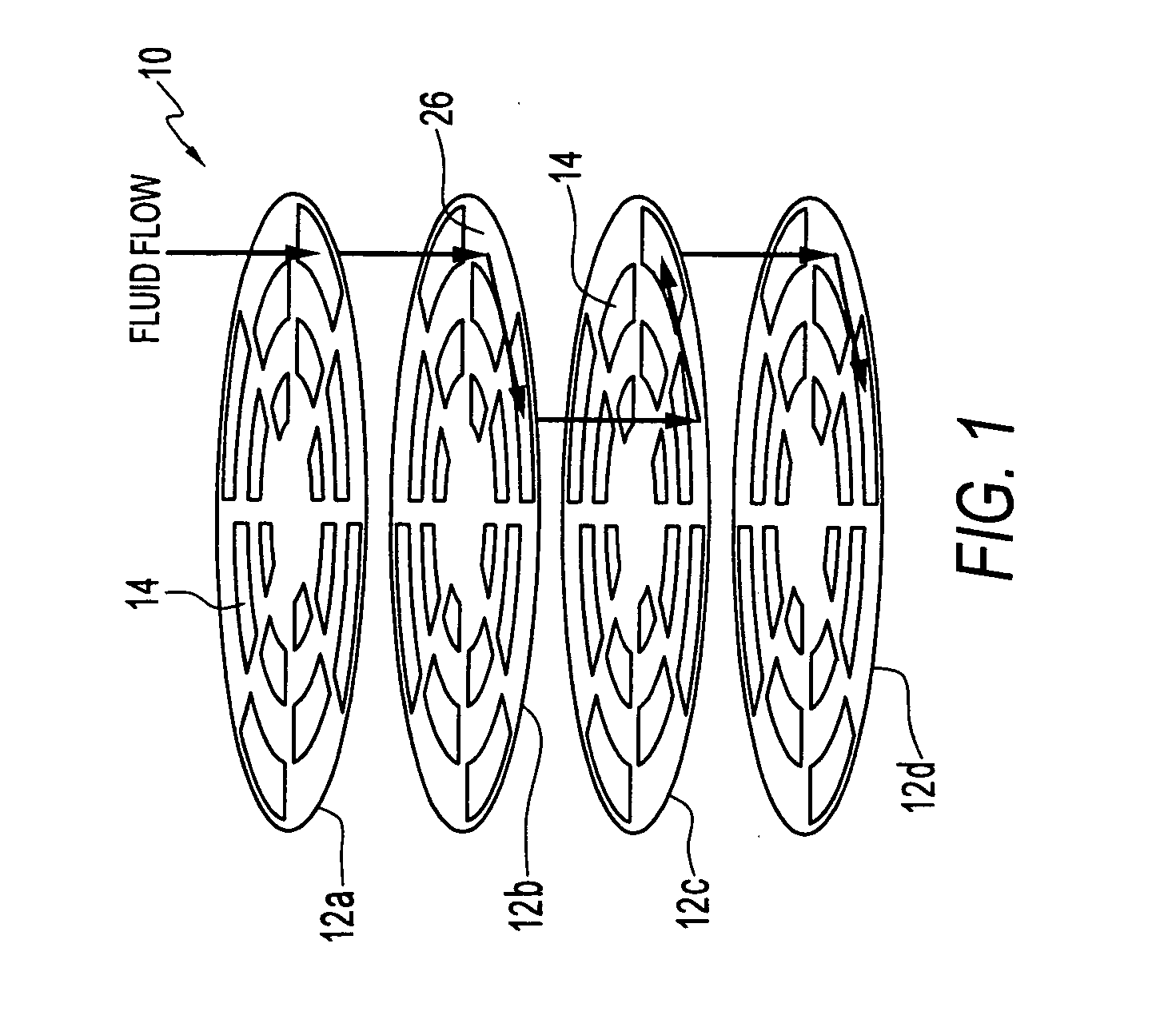
[0031] The invention concerns a collection device having a flow through micro scale plate arranged to collect analyte, and deliver a concentrated pulse of analyte to a detector system upon demand through heating. With the invention, analyte fluid flow is through at least one sorbent plate, which includes holes to pass analyte fluid flow, for example analyte vapor. Fluid flow for collection is generally perpendicular to the sorbent plate. Excellent interaction is achieved between the analyte fluid flow and a sorbent coating on the plate. After a period of collection, analyte may be provided to a detector system from the plate by heating the plate. Preferred embodiment plates include an integrated heater trace.

[0032] Embodiments of the invention use a series of two or more flow through micro scale plates. In preferred embodiments, a series of micro scale plates include a sorbent coating, and holes for analyte fluid flow through the plates. In preferred embodiments, individual plates ...


PUM

PropertyMeasurementUnit
pressure dropaaaaaaaaaa
diameteraaaaaaaaaa
thicknessaaaaaaaaaa

Abstract

In the invention, a collection device includes a first micro scale plate having a sorbent surface and a through hole. The through hole provides for the passage of an analyte fluid flow through the plate, and it has a volume and geometry to provide contact between the fluid and the sorbent surface in an amount effective to absorb a sufficient amount of analyte for subsequent detection of the analyte. The sorbent surface can be provided by a sorbent coating such as an active sensing film, e.g. a conducting or optically active material, examples of which include conducting polymers, polymer / carbon composites, carbon nanotubes, and dye-containing materials. The analyte collection device preferably includes a heating source, e.g. a heating element formed from a resistive trace, or a plurality of resistive traces, on or within the first microscale plate, for effecting a thermal release of collected analyte from the plate.

Description

REFERENCE TO RELATED APPLICATIONS AND PRORITY CLAIM [0001] This application is related to co-pending provisional application Ser. No. 60 / 477,032, filed on Jun. 10, 2003. Priority is claimed from that provisional application pursuant to 35 U.S.C. § 119. [0002] This application is also related to the application entitled MICRO SCALE FLOW THROUGH SORBENT PLATE COLLECTION DEVICE, filed on even date herewith.STATEMENT OF GOVERNMENT INTEREST [0003] This invention was made with Government assistance under NRL grant No. N00173-02-2-C002. The Government has certain rights in this invention.FIELD OF THE INVENTION [0004] A field of the invention is analyte collection. The invention is useful, for example, in analyte detection and analysis systems and methods, as might be used for the collection, detection and analysis of a wide range of vapors or gases, particulate and liquid bound analytes. Another field of the invention is analyte storage and delivery. The invention is useful, for example, t...

Claims


Application Information

Patent Timeline
Patent Type & Authority Applications(United States)
IPC IPC(8): B01L3/00G01N1/02G01N1/22G01N1/40G01N30/06G01N30/08G01N30/12G01N33/00
CPCB01L3/502753Y10T436/25B01L2200/10B01L2300/069B01L2300/1827B82Y30/00G01N1/02G01N1/2214G01N1/2273G01N1/40G01N1/405G01N30/08G01N33/0011G01N2001/022G01N2030/062G01N2030/121Y10T436/255B01L7/00
Inventor HOUSER, ERICMCGILL, ROBERT ANDREWNAGEL, DAVID
Owner NAVY U S A AS REPRESENTED BY THE SEC OF THE THE
Why Eureka
Try Eureka