Epoxy spray lining for liquid-cooled generator stator bar clips

a technology of stator bar clips and spray linings, which is applied in the direction of superimposed coating process, liquid/solution decomposition chemical coating, manufacturing tools, etc., can solve the problems of high labor intensity, high human-related defects, and leakage of stator bar ends and stator bar fittings (or clips)

a technology of stator bar clips and spray linings, which is applied in the direction of superimposed coating process, liquid/solution decomposition chemical coating, manufacturing tools, etc., can solve the problems of high labor intensity, high human-related defects, and leakage of stator bar ends and stator bar fittings (or clips)

US20050227009A1Inactive Publication Date: 2005-10-13GENERAL ELECTRIC CO

Image

  • Epoxy spray lining for liquid-cooled generator stator bar clips
  • Epoxy spray lining for liquid-cooled generator stator bar clips
  • Epoxy spray lining for liquid-cooled generator stator bar clips

Examples


Embodiment Construction

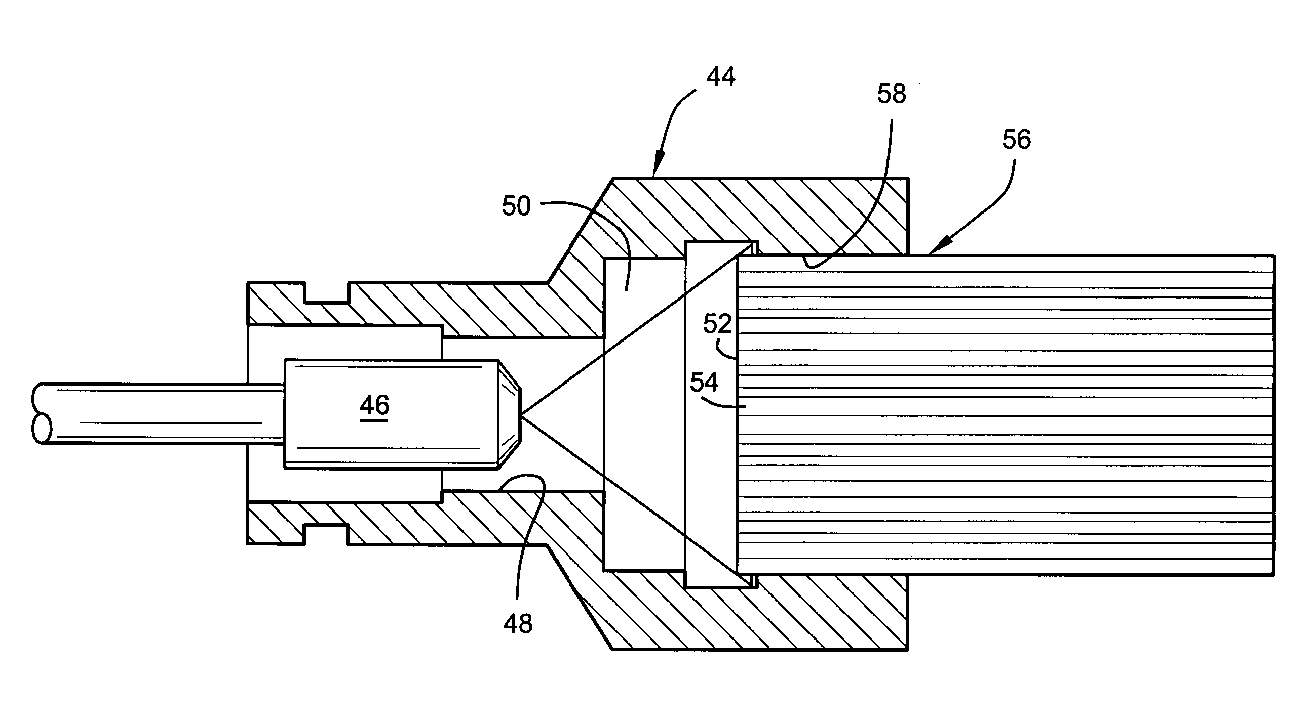
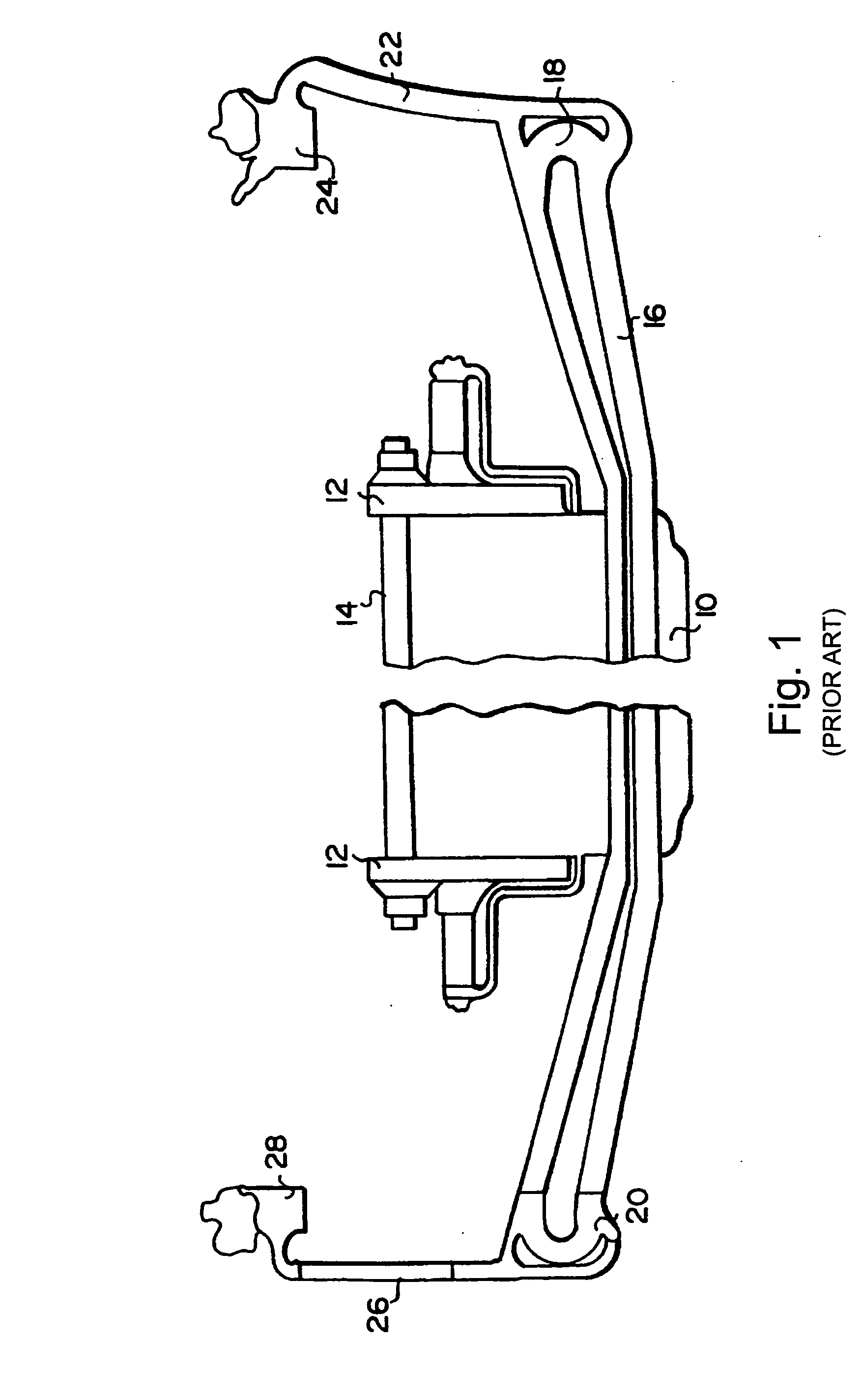
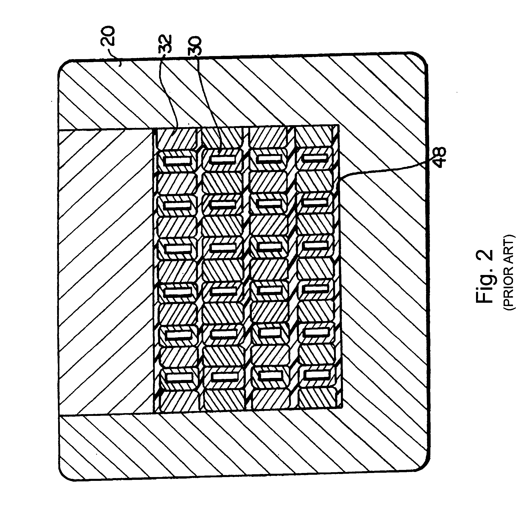
[0013] Referring now to the drawings, particularly to FIG. 1, there is illustrated a liquid-cooled stator winding arrangement used in a typical liquid-cooled generator. A typical stator core 10 has stator core flanges 12 and core ribs 14 with stator bars 16 passing through radially extending slots and terminating at opposite ends in end fittings 18 and 20. Inlet hoses 22 connect the inlet fitting or clip 18 to an inlet coolant header 24. Outlet hoses 26 connect the outlet fitting 20 to an outlet coolant header 28. As illustrated in FIG. 2, each stator bar 16 includes a plurality of hollow and solid copper strands 30 and 32, respectively, disposed in side-by-side and superposed relation one to the other. The fittings or clips 18 and 20 are similarly formed of an electrically conductive material such as copper. For purposes of this invention, only one of the fitting or clips needs to be described in detail. As best seen in FIGS. 2 and 3, the fitting 20 comprises a closed body having a...


PUM

PropertyMeasurementUnit
thicknessaaaaaaaaaa
thicknessaaaaaaaaaa
thicknessaaaaaaaaaa

Abstract

A method of coating a stator bar end inserted through an opening within a stator bar end fitting, the fitting having a chamber and the stator bar end having free ends of solid and hollow strands exposed within the chamber, the method including inserting a spray head nozzle through another opening in the fitting and in proximity to the free ends of the solid and hollow strands; spraying an epoxy resin composition so as to form a coating over the free ends of the solid and hollow strands and over at least a portion of adjoining wall surfaces of the fitting within the chamber; and curing the coating.

Description

BACKGROUND OF THE INVENTION [0001] The present invention relates to a method for creating a uniform epoxy lining on the end surface of liquid-cooling stator bar clip-to-strand braze joints. [0002] Water-cooled stator bars for electrical generators are comprised of a plurality of small rectangular solid and hollow copper strands which are brazed to one another and to an end fitting in which the strands are received. The end fitting serves as both an electrical and a hydraulic connection for the stator bar. The end fitting typically includes an enclosed chamber for ingress or egress of stator bar cooling liquid, typically deionized water. Another opening of the end fitting receives the ends of the strands of the stator bar, with the fitting and peripherally outermost copper strands of the stator bar being brazed to one another. Over time, leaks have developed about the connection between the stator bar ends and the stator bar fitting (or clip) as well as between adjacent strands. It i...

Claims


Application Information

Patent Timeline
13 Oct 2005
Publication
US20050227009A1
IPC
B05D5/00; B05D7/22; H02K3/24; H02K15/00; H02K15/12
CPC
B05D7/22; H02K15/12; H02K15/0093
Inventors
WANG, YU; MALL, WAHEED TONY