Eureka AIR delivers breakthrough ideas for toughest innovation challenges, trusted by R&D personnel around the world.

Surface-energy gradient on a fluid-impervious surface and method of its creation using a mixed monolayer film

a technology of surface energy gradient and fluid-impervious surface, which is applied in magnetic recording, material analysis, record information storage, etc., can solve the problems of increasing not solving the problem of fluid friction loss, and reducing the energy required to operate such systems. , to achieve the effect of reducing external forces, reducing energy consumption, and reducing energy consumption

Inactive Publication Date: 2005-10-13
BABCOCK BRIAN D
View PDF4 Cites 4 Cited by
  • Summary
  • Abstract
  • Description
  • Claims
  • Application Information

AI Technical Summary

Benefits of technology

[0019] The proposed system uses self-assembled monolayer (SAM) films to modify the surfaces of the channels; a novel design is proposed which modifies the channel using a mixed SAM surface so that fluids are transported with minimal or reduced external forces required. The proposed design will result in microfabricated systems that are smaller and more energy-efficient

Problems solved by technology

However, due to the microscopic scale of the systems involved, fluid transport and friction losses are problematic.
Each of these methods increases the energy required to operate such systems, and none of the methods solve the problem of fluid friction losses.
Therefore, as Dc begins to approach micron and angstrom dimensions, friction loss increases greatly.

Method used


Image

  • Surface-energy gradient on a fluid-impervious surface and method of its creation using a mixed monolayer film
  • Surface-energy gradient on a fluid-impervious surface and method of its creation using a mixed monolayer film
  • Surface-energy gradient on a fluid-impervious surface and method of its creation using a mixed monolayer film

Examples


Embodiment Construction

[0093] While this invention may be embodied in many different forms, there are described in detailed herein specific preferred embodiments of the invention. This description is an exemplification of the principles of the invention and is not intended to limit the invention to the particular embodiments illustrated.

[0094] As used herein, the term “tube” is any hollow object open on two sides without limitation by cross-sectional geometries.

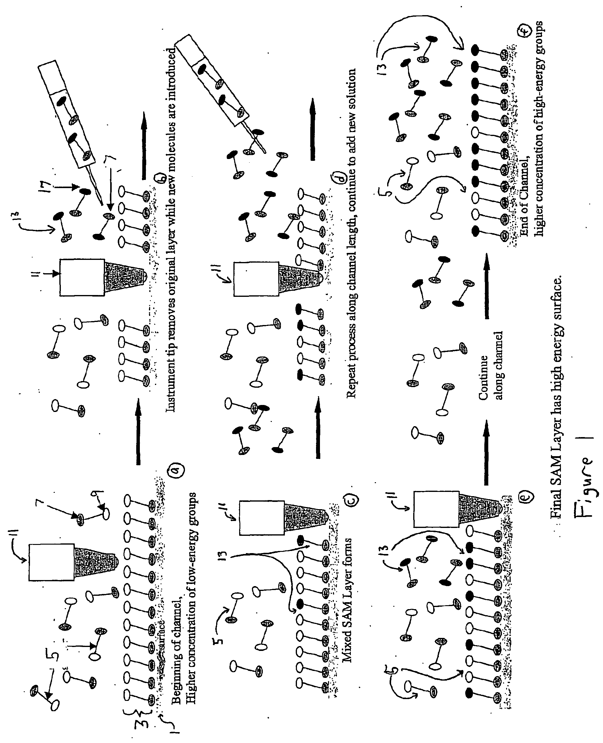
[0095] Turning now to the drawings, FIG. 1 shows a blown-up schematic view of an embodiment of the method for producing a mixed monolayer surface energy gradient. The view consists of 6 slides. Slide (a) shows a base surface 1 having a monolayer 3. The original monolayer is made up of a plurality of first organic molecules 5. The base surface 1 having a monolayer 3 can be stored and used later as well. The first organic molecules 5 are comprised of a functional group 7 (e.g. thiol) that reacts with the base surface 1 and a low surface energy func...


PUM

PropertyMeasurementUnit
contact angleaaaaaaaaaa
surface energyaaaaaaaaaa
molar ratioaaaaaaaaaa

Abstract

A surface energy gradient on a fluid-impervious surface and method of its creation comprising the steps of a) Exposing a base surface having a proximal and a distal portion to a first solution comprising at least one molecule of the formula X-J-M1 wherein X and M1 represent separate functional groups and J represents a spacer moiety that, together, are able to promote formation from solution of a self-assembled monolayer for sufficient time to form a monolayer surface [with] having a uniform surface energy on the base surface. b) Removing a portion of the monolayer of (a) such that a portion of the base surface is again fully or partially exposed. (c) Exposing the portion of the base surface from (b) to at least one other molecule including a functional group having a different surface energy from that of the functional group removed in (b) such that a surface energy gradient from a proximal location to a distal location is formed.

Description

CROSS-REFERENCE TO RELATED APPLICATIONS [0001] This application claims priority from the provisional application 60 / 335165 filed Nov. 1, 2001.STATEMENT REGARDING FEDERALLY SPONSORED RESEARCH [0002] Not Applicable BACKGROUND OF THE INVENTION [0003] This invention relates to a surface-energy gradient on a fluid-impervious surface and method of its creation. [0004] Microscopic fluidic devices, ranging from surgical endoscopes and microelectromechanical systems to the commercial ‘lab-on-a-chip’, allow chemical analysis and synthesis on scales unimaginable a few decades ago (Kataoka and Troian, 1999). Advances in microfabrication techniques have led to the ability to manufacture flow channels ranging from a few hundred angstroms to a few hundred microns (Pfahler, et al, 1990). However, due to the microscopic scale of the systems involved, fluid transport and friction losses are problematic. Different methods using temperature, pressure, or electric potential gradients have been developed...

Claims


Application Information

Patent Timeline
Patent Type & Authority Applications(United States)
IPC IPC(8): B01L3/00B05D1/18B05D3/00B05D3/12C07B61/00C12M1/34C12Q1/68
CPCB01J2219/00497Y10S977/858B01J2219/00527B01J2219/00605B01J2219/0061B01J2219/00612B01J2219/00621B01J2219/00626B01J2219/00637B01J2219/00657B01J2219/00659B01J2219/00722B01L3/502707B01L2300/16B01L2400/088B05D1/185B05D3/007B05D3/12B82Y30/00B82Y40/00C07B2200/11C12Q1/6837C40B40/00B01J2219/00511Y10S977/857Y10S977/962Y10T428/2438Y10T428/24802Y10T428/24413Y10T428/24355Y10T428/24405Y10T428/315Y10T428/24388Y10T428/26Y10T428/24479Y10T428/24545Y10T428/31C12Q2527/15C12Q2527/125C12Q2523/308
Inventor BABCOCK, BRIAN
Owner BABCOCK BRIAN D
Why Eureka
Eureka Blog
Learn More