
Method and apparatus for thermally controlling a mold, die, or injection barrel

a technology of injection molding and control system, which is applied in the direction of domestic cooling apparatus, heating types, instruments, etc., can solve the problems of limiting the precision and reliability of the temperature control process, and achieve the effects of reducing the cost or inefficiency of conventional systems, reducing the loss of slippage, and reducing the cost of operation

Active Publication Date: 2012-02-14
MOLDCOOL INT
View PDF26 Cites 11 Cited by
  • Summary
  • Abstract
  • Description
  • Claims
  • Application Information

AI Technical Summary

Benefits of technology

"The invention is a new temperature control system for molding machines that uses a digital servo stepping motor and a positive displacement pump to control the temperature of the fluid being directed to the mold. This system is more precise and reliable than previous methods because it compensates for variations in pressure and voltage by adjusting the volume of fluid in real time. The system also uses a smaller, more efficient servo motor and a smaller positive displacement pump, reducing energy consumption and inefficiency. The circulator in this system uses a low-energy consumption metering of coolant, eliminating the need for a central chilling system. The system allows for programming behavior and adjusting the flow rate of fluid in real time based on sensor data. The circulator can be used with conventional direct injection or heat exchanger techniques and can also adjust the quantity of fluid injected to maintain control loop temperature in processes that vary in timing or thermal output."

Problems solved by technology

However, the effectiveness of these techniques varies considerably based on system design, component selection, and overall operating conditions, as described in the background section, all of which limits the precision and reliability of the temperature control process.

Method used


Image

  • Method and apparatus for thermally controlling a mold, die, or injection barrel
  • Method and apparatus for thermally controlling a mold, die, or injection barrel
  • Method and apparatus for thermally controlling a mold, die, or injection barrel

Examples


Embodiment Construction

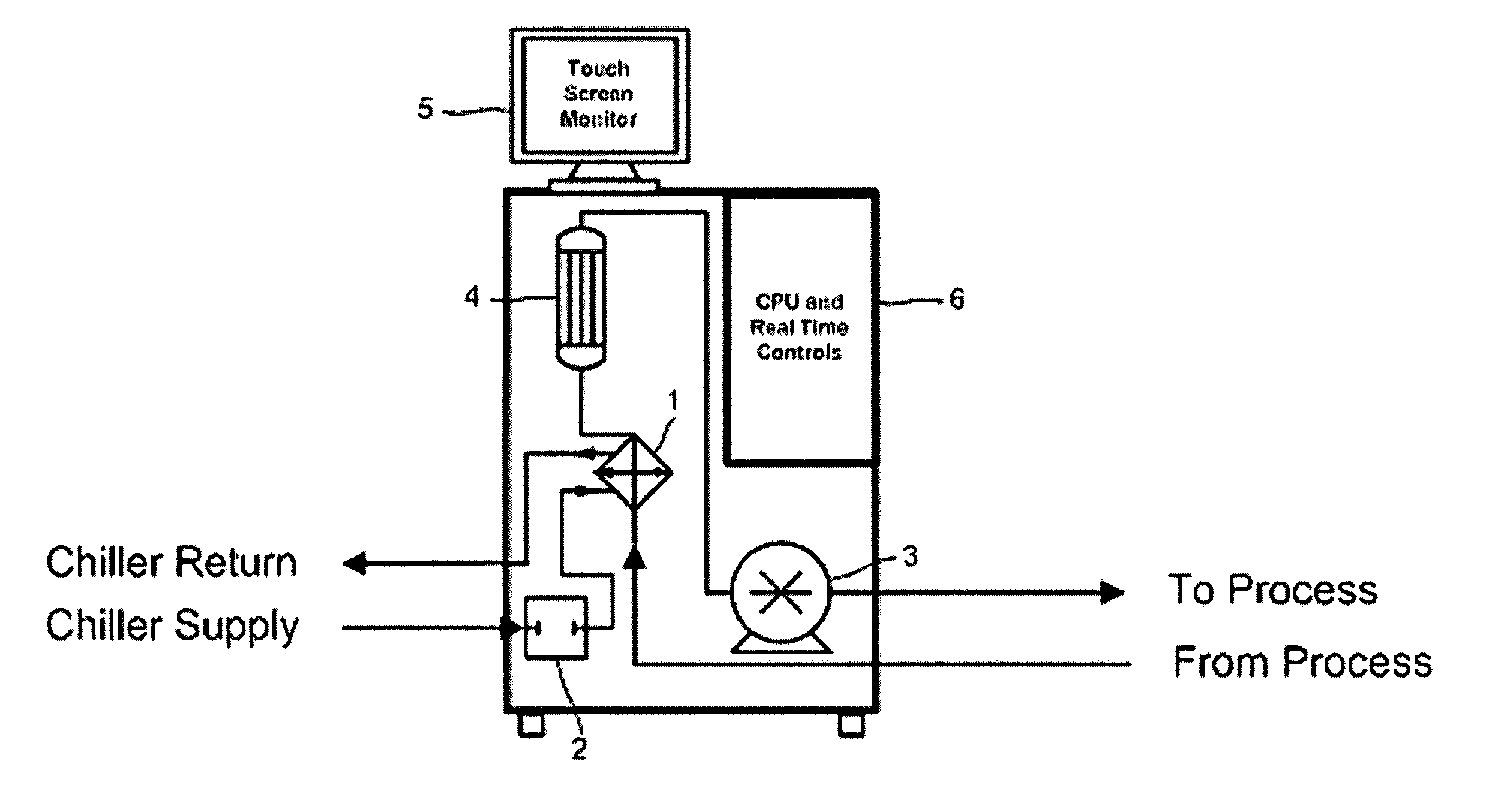
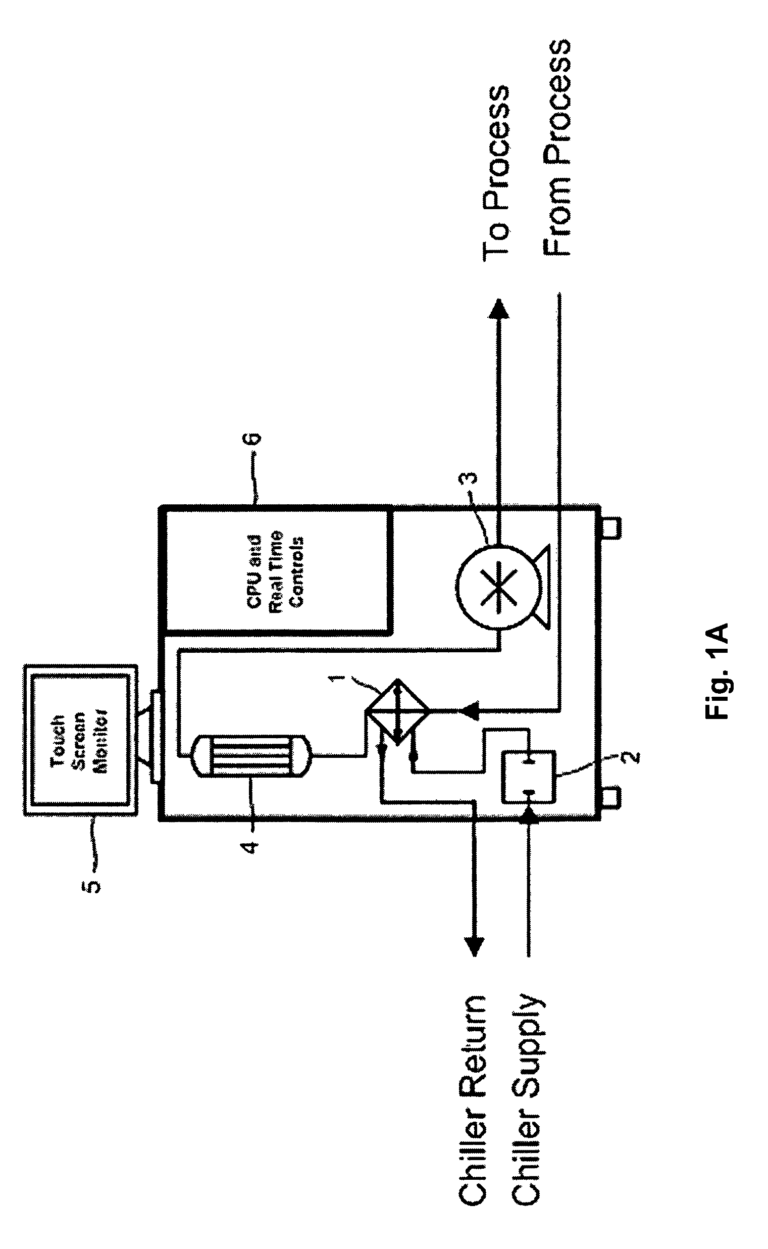
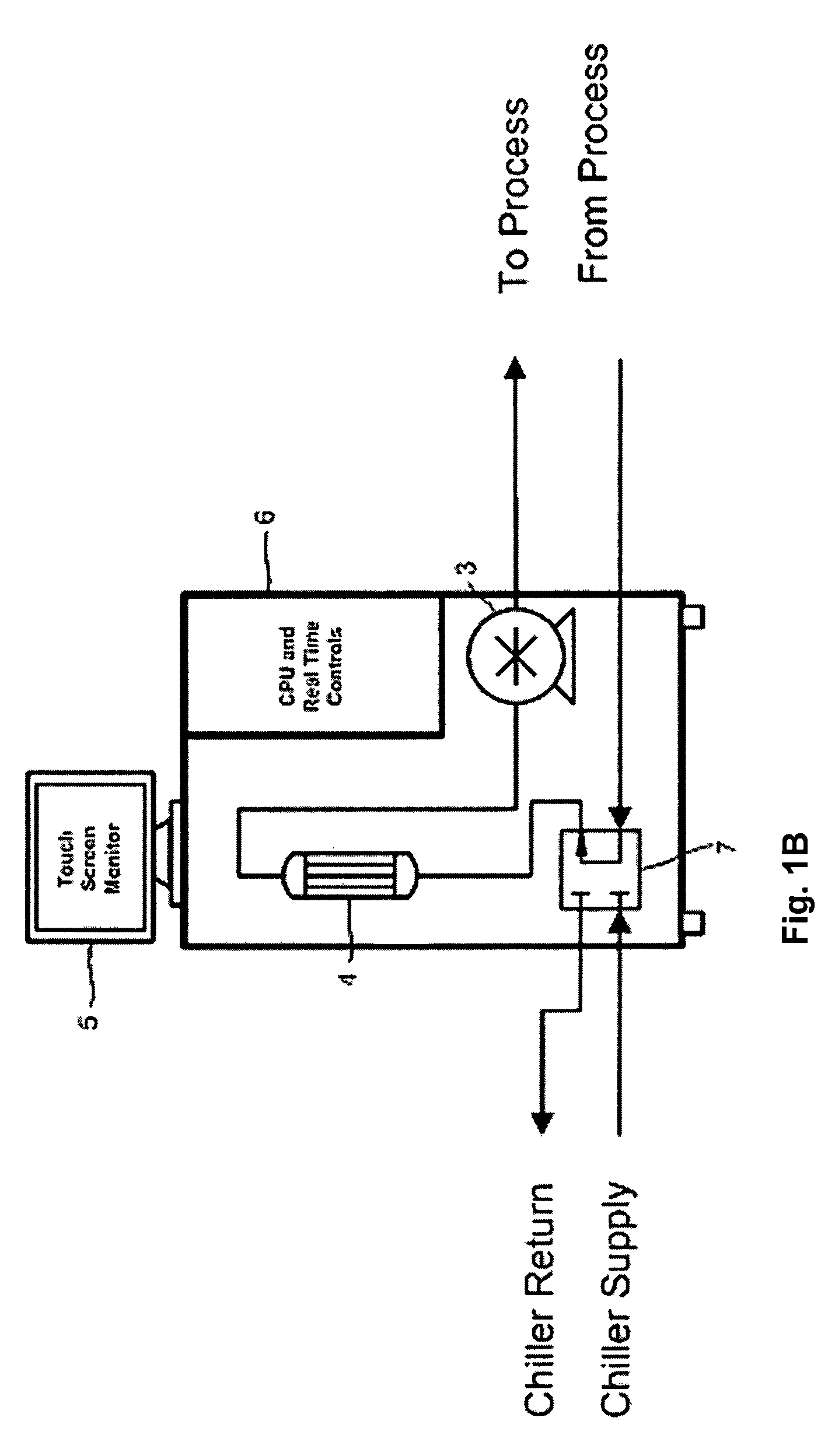
[0033]One embodiment of the present invention provides a servo stepping motor operating a positive displacement thermal control fluid pump as part of an injection molding temperature control system, commonly called a “circulator” or circulator system. A servo stepping motor is somewhat tolerant of supply line voltage fluctuations that will vary the speed of a conventional motor. The positive displacement pump meters exact quantities of thermal control fluid or coolant in proportion to controlled revolutions of the stepping motor. This circulator system is used to control the temperature of a mold, die or injection barrel by circulating a fluid medium, at a suitably lower or higher temperature depending on whether the process is exothermic or endothermic, through a network of channels in the mold in the conventional manner, adding or extracting heat from the mold. The loop of pre-heated or pre-cooled fluid that is plumbed from the circulator pump to the mold, die or injection barrel ...


PUM

PropertyMeasurementUnit
temperatureaaaaaaaaaa
thermalaaaaaaaaaa
energy set pointaaaaaaaaaa

Abstract

A method and apparatus are disclosed for managing thermal energy transfer between a mold, die or cavity and a thermal transfer fluid. The thermal energy being exchanged with the mold, die or cavity is calculated in real time as a function of the temperature differential between inlet and outlet fluid temperatures, the volumetric rate of fluid delivery, and known characteristics of the fluid. The rate of thermal energy exchange is controlled by varying the fluid delivery rate in accordance with a desired thermal energy exchange profile.

Description

FIELD OF THE INVENTION[0001]The invention relates to thermal control systems and methods for exerting thermal control, and more particularly, to thermal control systems and methods for use with an injection molding apparatus.BACKGROUND OF THE INVENTION[0002]A thermal fluid circulator in the context of the invention is a device or system that is commonly used in the plastics, metals, ceramics, and die cast molding industries in the control of operating temperatures of molds, dies or injection barrels. Circulator systems may incorporate a built-in chiller. Central chilling systems need a main circulator pumping system. Alternatively, they are also built using water tower evaporative cooling technology. Circulators are also used in other industries besides plastics for similar temperature control purposes. Sometimes circulators are used for controlling the operating temperatures in a two component mixing process such as molding liquid silicone rubber or LSR and sometimes called LIM, wh...

Claims


Application Information

Patent Timeline
Patent Type & Authority Patents(United States)
IPC IPC(8): B29C47/92B29C48/92
CPCB29C35/007B29C45/7306B29C47/92G05D23/1919B29C2945/76545B29C2945/76782
Inventor JOHNSON, KENNETH E.
Owner MOLDCOOL INT
Learn More