High agility frequency synthesizer phase-locked loop

a phase-locked loop, high-agile technology, applied in the direction of oscillator generators, pulse automatic control, electrical equipment, etc., can solve the problem of strained traditional frequency generation circuits, inability to rapidly generate signals at different frequencies, inability to rapidly change the frequency of signals, etc., to achieve low cross-coupling and high agility low phase noise frequency synthesizer

Active Publication Date: 2005-10-13
SKYWORKS SOLUTIONS INC
View PDF66 Cites 14 Cited by
  • Summary
  • Abstract
  • Description
  • Claims
  • Application Information

AI Technical Summary

Benefits of technology

[0010] A highly agile low phase noise frequency synthesizer is disclosed. As an advantage over the prior art, the frequency synthesizer disclosed herein is capable of rapidly generating signals at different output frequencies while maintaining low cross-coupling. In one embodiment two or more signal generators utilize a reference frequency to generate two or more signals which are provided to a switch. The system switches between these signals to rapidly output a signal at a desired frequency.

Problems solved by technology

While these circuits worked well in prior art communication systems, the demands of modem communication devices, and the communication protocols employed, have strained the capability of traditional frequency generating circuits.
One drawback revealed by prior art signal generation systems, for a given cost target, is an inability to rapidly generate signals at different frequencies, i.e. change a signal's frequency, even when the frequencies are relatively close.
Prior art PLL circuits are simply unable to rapidly change the frequency of their output signals, even when the change in frequency is quite small.
An undesirably slow rate of change of a PLL can be a significant disadvantage and result in inoperability with certain systems.
This proposed solution, however, also has drawbacks.
One such drawback is that two or more PLLs create interference, such as EMI, that cross contaminate the synthesized signals.
This generates undesirable spurious tones and phase noise, or generation of spurious signals that can result in the generated signals being unusable by precision oriented communication transceivers.
While this solution has been widely adopted, it increases the cost of the signal generating systems.
Moreover, the size and complexity of the signal generation system is increased as are the number of circuit board traces required for implementation.
As is generally understood, an implementation utilizing discrete components located in an EMI shielded enclosure is not a desirable solution to a prior art problem in the electronic arts.
Thus, there is an unsatisfied need in the art for a method and apparatus to generate a highly agile, low phase noise, frequency specific, signal synthesizer.

Method used


Image

  • High agility frequency synthesizer phase-locked loop
  • High agility frequency synthesizer phase-locked loop
  • High agility frequency synthesizer phase-locked loop

Examples


Embodiment Construction

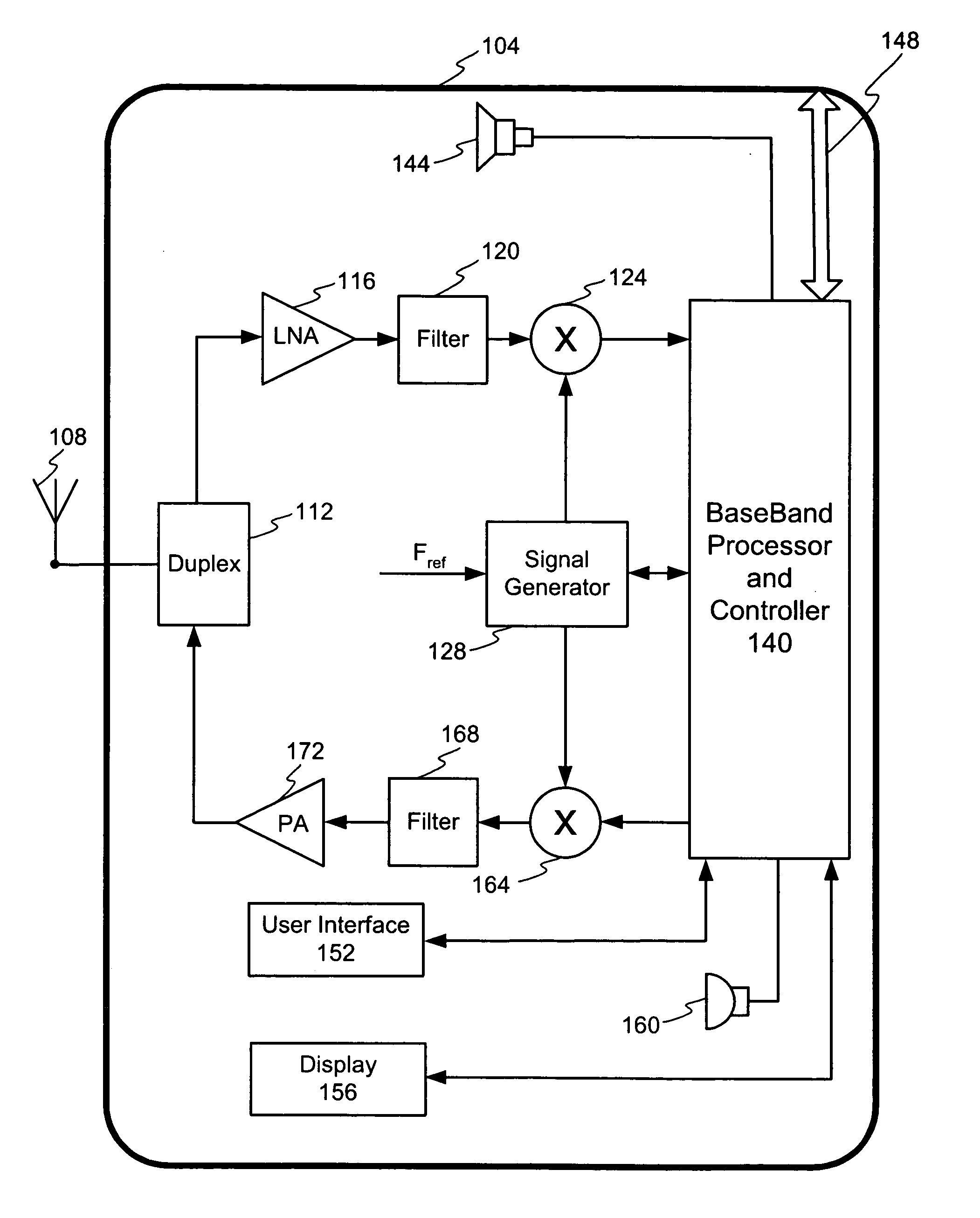
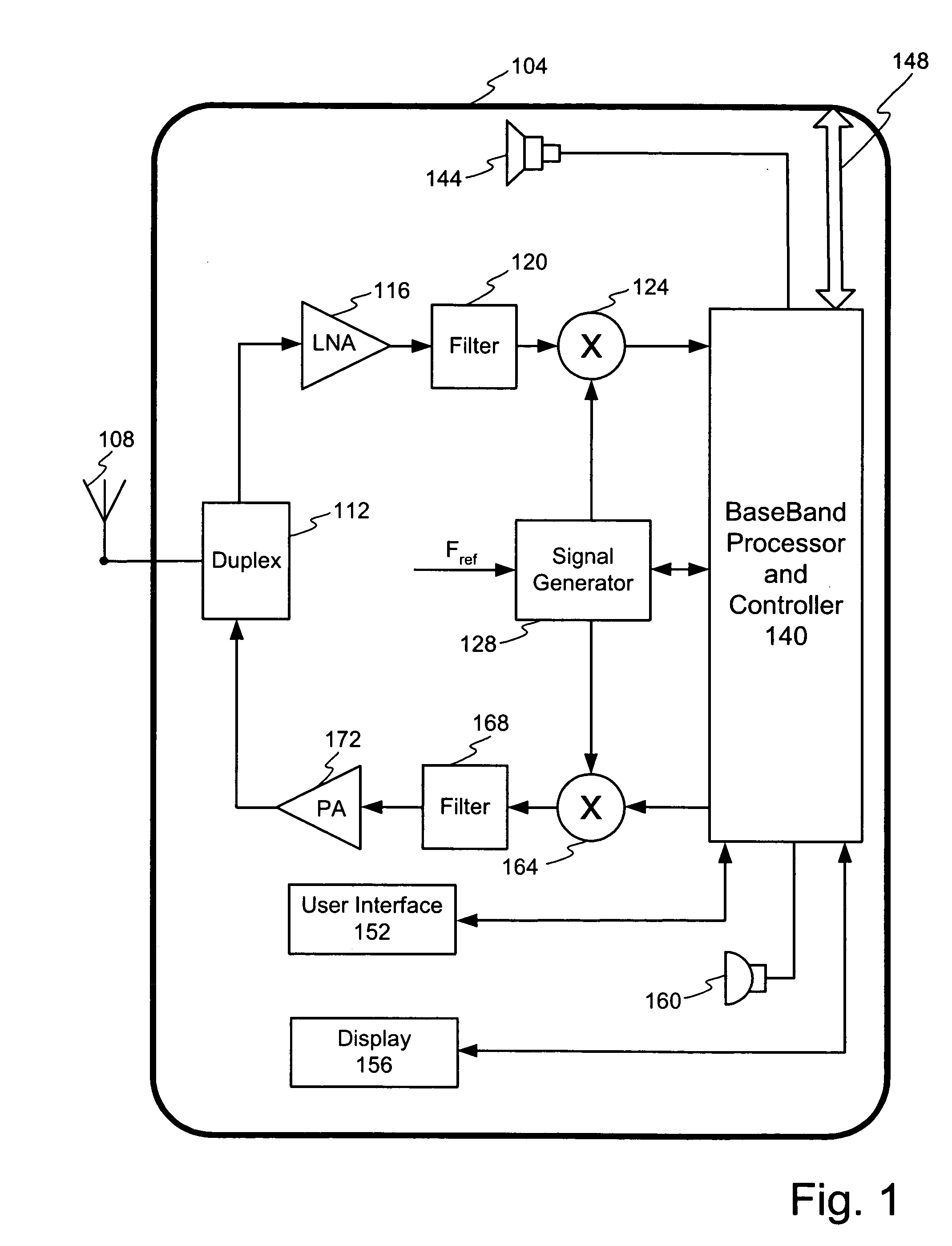
[0035]FIG. 1 illustrates a block diagram of a first example environment of use of the invention. The example environment shown in FIG. 1 comprises a wireless communication device but it is noted that this is but one possible example environment of use. It is contemplated that the invention may find use and benefit in numerous other environments both in the communication field and other fields of use.

[0036] The embodiment of a wireless communication device shown in FIG. 1 comprises an outer housing 104 configured to protect and selectively enclose the internal electronic apparatus. An antenna 108 receives incoming signals and transmits outgoing signals. The antenna 108 may be located inside or outside of the housing 104. A duplexer 112 connects to the antenna 108 to route incoming signals to a receiver apparatus, shown as the upper path from the duplexer 112 and route outgoing signals to the antenna.

[0037] The duplexer 112 connects to a receiver apparatus to hereby route received s...


PUM


Abstract

A highly agile low phase noise frequency synthesizer is provided for rapid generation of frequency specific signals. The frequency synthesizer is capable of rapidly generating signals at different output frequencies while maintaining low cross-coupling. Two or more signal generators utilize a reference frequency to generate two or more signals. These signals are limit processed to reduce cross-coupling prior to being presented to a switch. Responsive to a control signal, the switch outputs one of the signals to a frequency modification device, such as a frequency divider or multiplier. Responsive to a control signal, the frequency modification device scales the frequency of the switch output to convert the frequency of the switch output signal to a desired output frequency. By maintaining sufficient frequency separation between the switch input signals cross-coupling and phase noise is minimized and implementation on an integrated circuit may be achieved.

Description

1. FIELD OF THE INVENTION [0001] The invention relates to communication systems and circuits, and in particular to a method and apparatus for rapid generation of frequency specific signals. 2. RELATED ART [0002] To obtain the desired information during reception of a signal, communication devices often isolate a signal which is located at a particular frequency. Likewise, during transmission of a signal, a communication device may utilize one or more signals at precise frequencies to modulate the outgoing signals to a desired carrier frequency. These are but a few of the numerous communication operations and signal processing tasks that rely on generation and use of a signal at a precise frequency. [0003] In addition, modern communication devices often utilize numerous signals at different frequencies. For example, code hopping communication protocols often shift or change the frequency of the signal. Other instances, when it may be necessary to utilize a different frequency, are wh...

Claims


Application Information

Patent Timeline
Patent Type & Authority Applications(United States)
IPC IPC(8): H03L7/22H04B1/38
CPCH03L7/22
Inventor ALI, AKBARYOUNG, JAMES P.
Owner SKYWORKS SOLUTIONS INC
Why Eureka
Try Eureka