Connections and feeds for broadband antennas

a broadband antenna and connection technology, applied in the direction of resonant antennas, non-resonant long antennas, waveguide types, etc., can solve the problems of special techniques for converting between a balanced mode and an unbalanced mode, and achieve the effects of low cross-coupling, low loss, and equal electrical length and impedan

Inactive Publication Date: 2005-01-27
RGT UNIV OF CALIFORNIA
View PDF24 Cites 5 Cited by
  • Summary
  • Abstract
  • Description
  • Claims
  • Application Information

AI Technical Summary

Benefits of technology

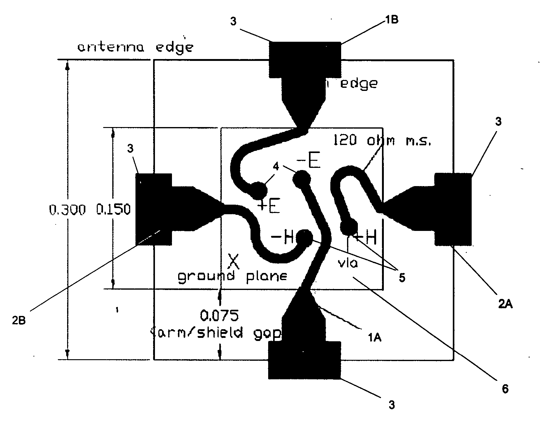
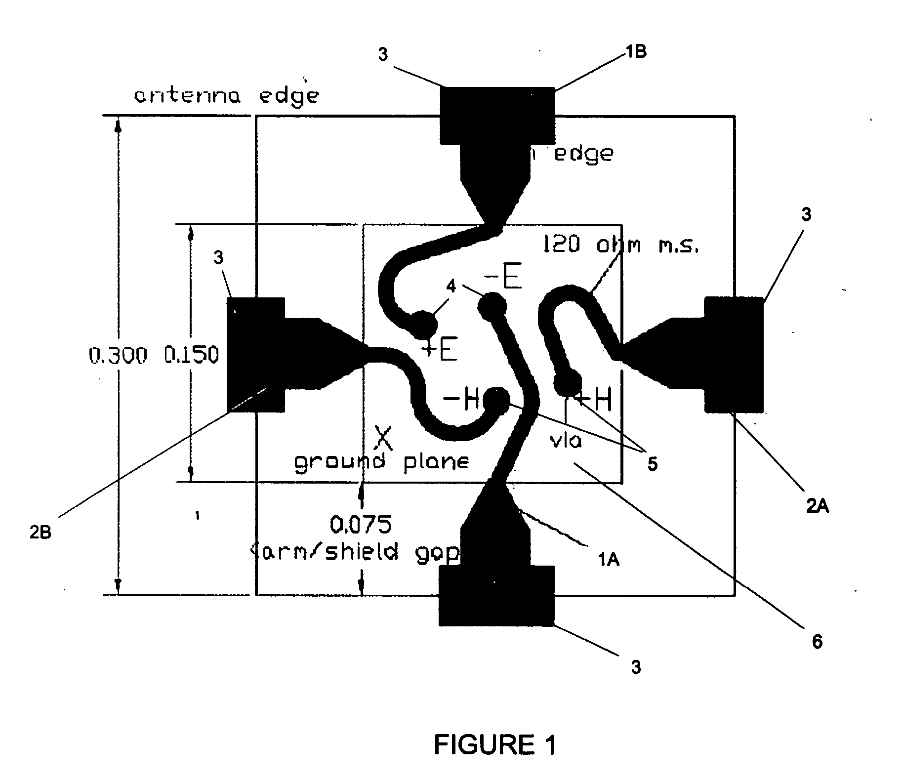
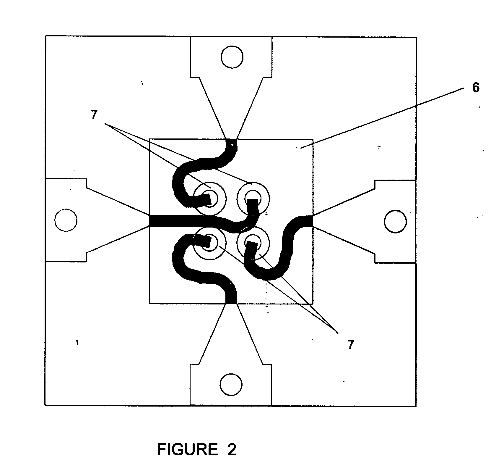
[0010] Various embodiments of a planar circuit board are described containing electrically conducting traces or probes delivering the signal from the terminals of the antenna to holes or RF vias for connection to a transmission line. An object of the present invention is to provide a planar circuit board whose probes have substantially equal electrical length and impedance. Other objectives include providing a planar circuit board whose probes have low losses and low cross-coupling between polarization modes.

Problems solved by technology

Many antennas generate balanced signals across their input terminals requiring the inclusion of a balun between the terminals and an amplifier, detector or other electronics that typically require unbalanced input.
The impedance transformation can be performed by a variety of well-known techniques, but the conversion between a balanced mode and an unbalanced mode typically requires special techniques.

Method used


Image

  • Connections and feeds for broadband antennas
  • Connections and feeds for broadband antennas
  • Connections and feeds for broadband antennas

Examples


Embodiment Construction

[0024] After considering the following description, those skilled in the art will clearly realize that the teachings of the invention can be readily utilized in connecting and / or impedance matching a balanced transmission circuit with an unbalanced transmission circuit as typically arising in connections to the feed of a broadband antenna.

[0025] The bandwidth of a microwave reflector telescope is typically limited by the size and figure accuracy of the mirror elements and by the feed which couples focused radiation to the receiver. A single or hybrid-mode feedhorn can effectively illuminate a telescope aperture with low ohmic loss. However, its gain typically varies quadratically with frequency, limiting its effective bandwidth to typically less than an octave.

[0026] A log-periodic (LP) antenna can be designed to illuminate a telescope aperture over multi-octave bandwidths, but may have greater spillover and ohmic loss than a well-designed feedhorn. Moreover, in contrast to a horn...


PUM


Abstract

The present invention relates to connecting and impedance matching a balanced electrical signal, such as that received by an antenna, with an unbalanced transmission circuit, such as that delivered to an amplifier. A planar circuit board is described that delivers signals having opposite polarization collected by different antenna arms to a location for convenient connection to a twin-lead transmission line. Circuit topologies for the circuit board are described that provide relatively low loss and low cross-coupling. A tapered microstrip balun is also described that includes two conducting microstrips on opposing faces of a dielectric separator. Stepped or tapered microstrips at the balanced input port of the balun provide an impedance transforming section electrically connecting to a mode transducing section, in which one of the microstrips tapers outward to form a substantially wider strip. Appropriate choice of parameters is shown to lead to favorable performance in a compact balun.

Description

CROSS REFERENCE TO RELATED APPLICATION [0001] Pursuant to 35 U.S.C § 119, this application claims priority from provisional patent application Ser. No. 60 / 478,888, filed Jun. 16, 2003, the entire contents of which is incorporated herein by reference for all purposes.BACKGROUND OF THE INVENTION [0002] 1. Field of Invention [0003] This invention relates generally to the field of interconnecting broadband antennas with detection or transmission electronics and, more particularly, to baluns and other devices for effecting such interconnections. [0004] Financial support from the SETI Institute, made possible by the Paul G. Allen Foundation, is gratefully acknowledged. [0005] 2. Description of the Prior Art [0006] Many antennas generate balanced signals across their input terminals requiring the inclusion of a balun between the terminals and an amplifier, detector or other electronics that typically require unbalanced input. A “balun” is basically an impedance transformer designed to coup...

Claims


Application Information

Patent Timeline
Patent Type & Authority Applications(United States)
IPC IPC(8): H01P5/10H01Q1/38H01Q9/28
CPCH01P5/10H01Q9/28H01Q1/38
Inventor ENGARGIOLA, GREGORY
Owner RGT UNIV OF CALIFORNIA
Why Eureka
Try Eureka