Car-mounted electronic control device

a technology of electronic control device and electronic control device, which is applied in electrical control, generating/distributing signals, horology, etc., can solve the problems of increasing the power consumption and the number of parts, complicated and expensive construction, and high price of electronic control device, so as to eliminate the influence of individual dispersion fluctuation, and high precision

Active Publication Date: 2005-10-13
MITSUBISHI ELECTRIC CORP
View PDF7 Cites 20 Cited by
  • Summary
  • Abstract
  • Description
  • Claims
  • Application Information

AI Technical Summary

Benefits of technology

[0020] In the car-mounted electronic control device thus far described according to the invention, the pulse period of the high-speed clock signal by the first oscillator is estimated during the action of the main CPU with reference the multiplied / divided pulse period of the highly precise reference clock for driving the main CPU. Of the individual dispersion fluctuation and the environmental temperature characteristic fluctuation of the first oscillator, it is possible to eliminate the influences of the individual dispersion fluctuation.
[0021] Moreover, the pulse period of the low-speed clock signal by the second oscillator is periodically estimated with reference to the pulse period of the high-speed clock signal after the actions top of the main CPU. It is, therefore, possible to eliminate the influences of the individual dispersion fluctuation of the second oscillator and the environmental temperature characteristic fluctuation.

Problems solved by technology

The external oscillator, however, increases the power consumption and the number of parts, causing the electronic control device to be a high price.
Therefore, the clock generator causes a complicate and expensive construction just for a timing application.

Method used


Image

  • Car-mounted electronic control device
  • Car-mounted electronic control device
  • Car-mounted electronic control device

Examples


embodiment 1

of the Invention

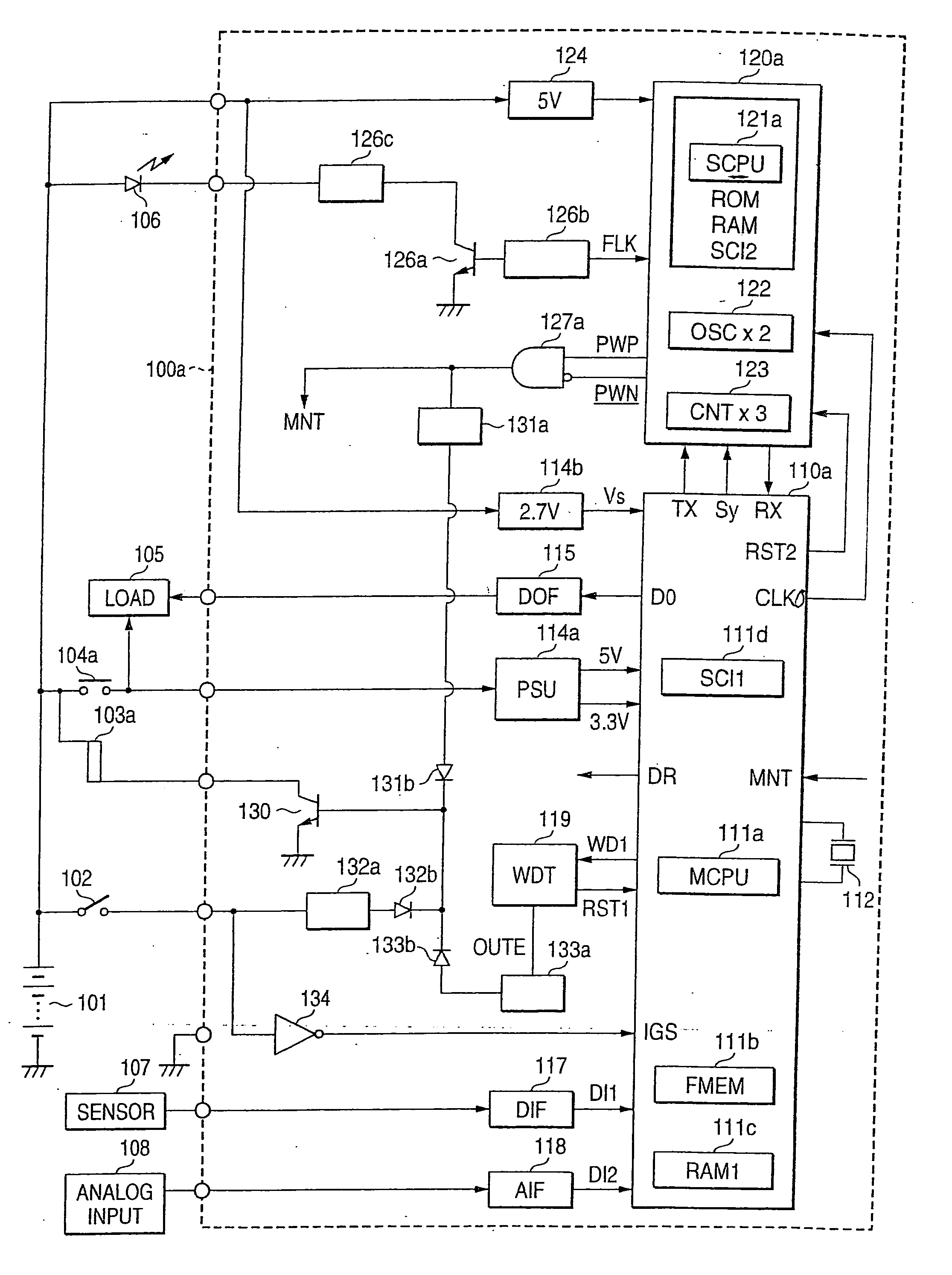
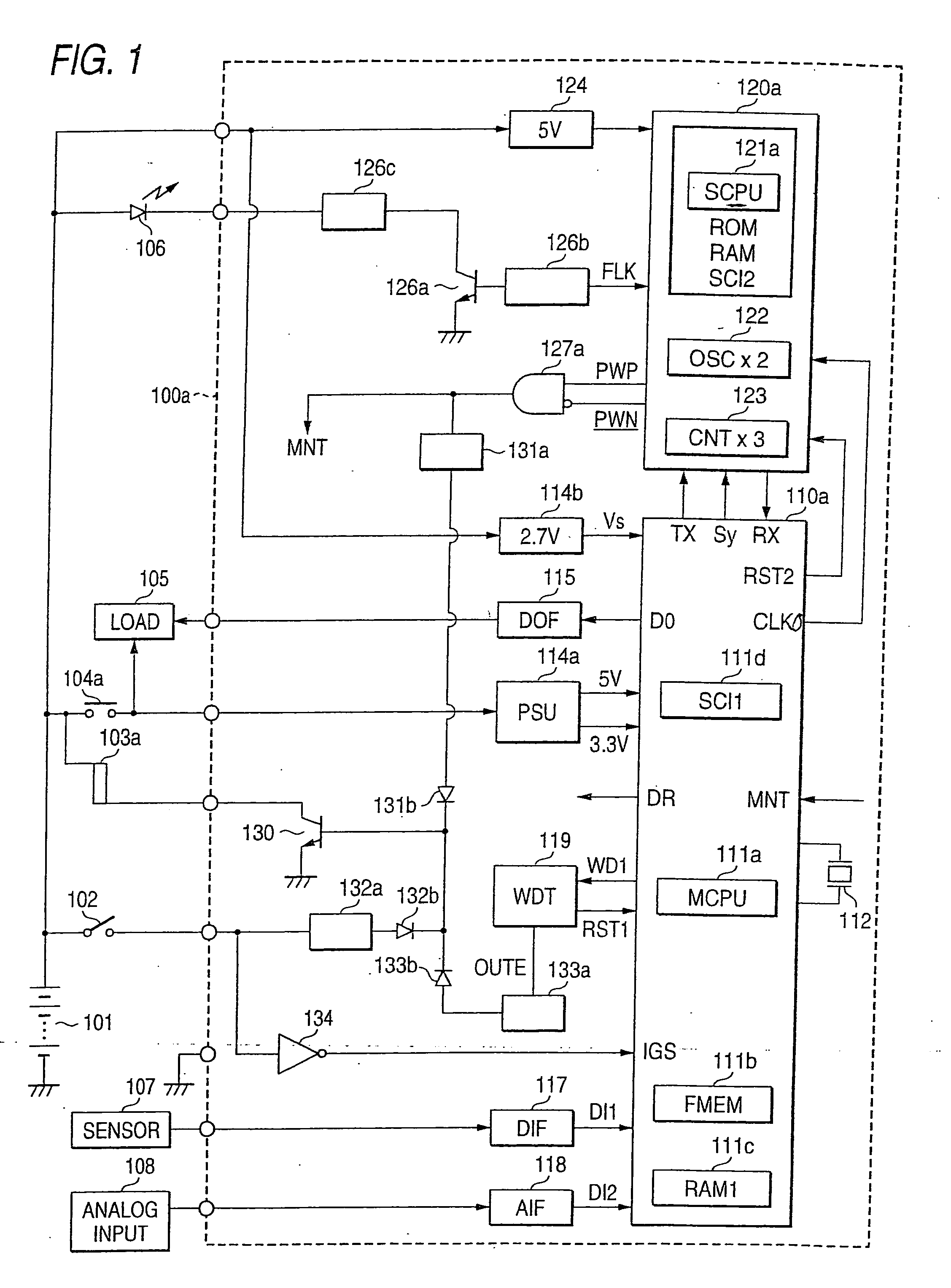
[0035]FIG. 1 showing the entire construction diagram of the electronic control device according to the first embodiment of the invention will be described in the following. In FIG. 1, a car-mounted electronic control device 100a is mainly constructed of a main control circuit unit 110a and a timer circuit unit 120a, and is housed in the not-shown sealed housing. External devices to be connected with the car-mounted electronic control device 100a include a car-mounted battery 101, a power source switch 102, an electromagnetic coil 103a to act as a power source relay, a switching element 104a or an output contact of the electromagnetic coil 103a, various electric loads 105 such as a display device or an actuator, various input sensors 107 including various operation switches for ON / OFF operations, an analog input sensor 108, and a display device 106 of a light emitting diode. The main control circuit unit 110a is constructed to include a main CPU 111a such as a micropr...

embodiment 2

of the Invention

[0170]FIG. 9 presenting the entire construction diagram of an electronic control device according to the second embodiment of the invention will be described in a manner to centralize the points different from those of FIG. 1.

[0171] In FIG. 9, a car-mounted electronic control device 100b is mainly constructed of a main control circuit unit 10b and a timer circuit unit 120b, and is housed in the not-shown sealed housing.

[0172] At first, an output contact 104b of a power source relay having an electromagnetic coil 103b is connected with the main power source circuit 114a through a reverse current blocking diode 140, thus constructing a first feed circuit from the car-mounted battery 101.

[0173] The main control circuit unit 110b is constructed to include a first program memory 111e of an on volatile flash memory associated with the main CPU 111a, an operation processing RAM memory 111c, and a series-parallel converter 111d, and generates a self-holding drive signal D...


PUM


Abstract

The car-mounted electronic control device is constructed to include a main control circuit unit to be powered with a car-mounted battery through a switching element and a main power source circuit, and a starting timer circuit unit powered at all times through an auxiliary power source circuit. The timer circuit unit is provided with a sub CPU for acting in synchronism with a high-speed clock signal, and a timing counter for counting the frequency-divided signal of a low-speed clock signal. When a power source switch is opened to interrupt a switching element, the timer circuit unit measures a target awakening time periodically by contrasting the period of the low-speed clock signal to the period of the high-speed clock signal.

Description

BACKGROUND OF THE INVENTION [0001] 1. Field of the Invention [0002] The present invention relates to a car-mounted electronic control device, in particular, to improvements in a starting control for measuring a target awakening time so as to prevent a preheat control of cooling water or a detection of evaporation of a fuel from being left for a long time, and more particularly, to a car-mounted electronic control device capable of making a start control with a low power consumption, in a high precision and at a low cost. [0003] 2. Description of the Related Art [0004] In the related art, there is well known a car-mounted electronic control device which comprises: a main control circuit unit including a microprocessor to become a main CPU powered by a car-mounted battery through a switching element responding to the action of a power source switch and a main power source circuit, for driving various electric loads in response to the action states of various input sensors and the cont...

Claims


Application Information

Patent Timeline
Patent Type & Authority Applications(United States)
IPC IPC(8): G04F10/00B60L1/00B60R16/02B60R16/03F02D45/00G04G15/00G06F1/08G06F1/10G06F1/26G06F1/32H04N9/89
CPCB60R16/03G04G15/00G06F1/263G06F1/10G06F1/08
Inventor SAYAMA, MASAHIKOKANZAKI, SHOZO
Owner MITSUBISHI ELECTRIC CORP
Why Eureka
Try Eureka