Structural braced frame wall panel system

a structural brace and wall panel technology, applied in the direction of girders, building repairs, shock proofing, etc., can solve the problems of reducing the strength of structural components, reducing the strength of structural components, so as to achieve the effect of reducing the strength of compressive and tension forces

Inactive Publication Date: 2005-10-20
MAJLESSI KAMRAN REZA
View PDF12 Cites 16 Cited by
  • Summary
  • Abstract
  • Description
  • Claims
  • Application Information

AI Technical Summary

Benefits of technology

[0005] In accordance with the present invention there is provided a panelized wall system with diagonal members that can meet seismic building standards for the construction of multistory buildings. The panelized wall system comprises vertical and horizontal studs with diagonal members to provide additional strength against compressive and tension forces. In order to meet seismic requirements, each of the vertical studs includes a reinforced opening through which a diagonal member extends through. In this respect, the gravity loads of the structure are not transferred to the diagonal members by the vertical studs because the vertical studs are not connected to the diagonal members. It is therefore possible to build multistory structures with a panelized wall system and still provide the necessary strength required by seismic building codes.

Problems solved by technology

In this arrangement, the diagonal members can only provide resistance to tension forces in one direction.
Due to building requirements, this type of arrangement cannot be used for two story structures.
Also, the strap usually adds thickness to the wall panel which complicates the finishing of the structure.
However, the threaded rods suffer the same drawbacks as the strap.
Specifically, the threaded rod can only take tension loads and will buckle under compressive loads.
The threaded rod is therefore not adequate to meet seismic building codes.
Furthermore, the threaded rods add thickness to the building panel thereby complicating construction.

Method used


Image

  • Structural braced frame wall panel system
  • Structural braced frame wall panel system
  • Structural braced frame wall panel system

Examples


Embodiment Construction

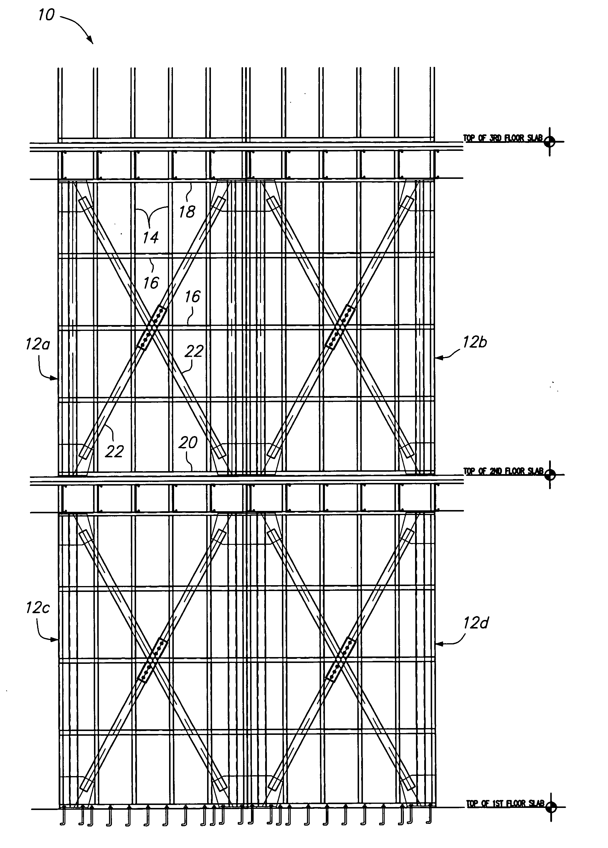
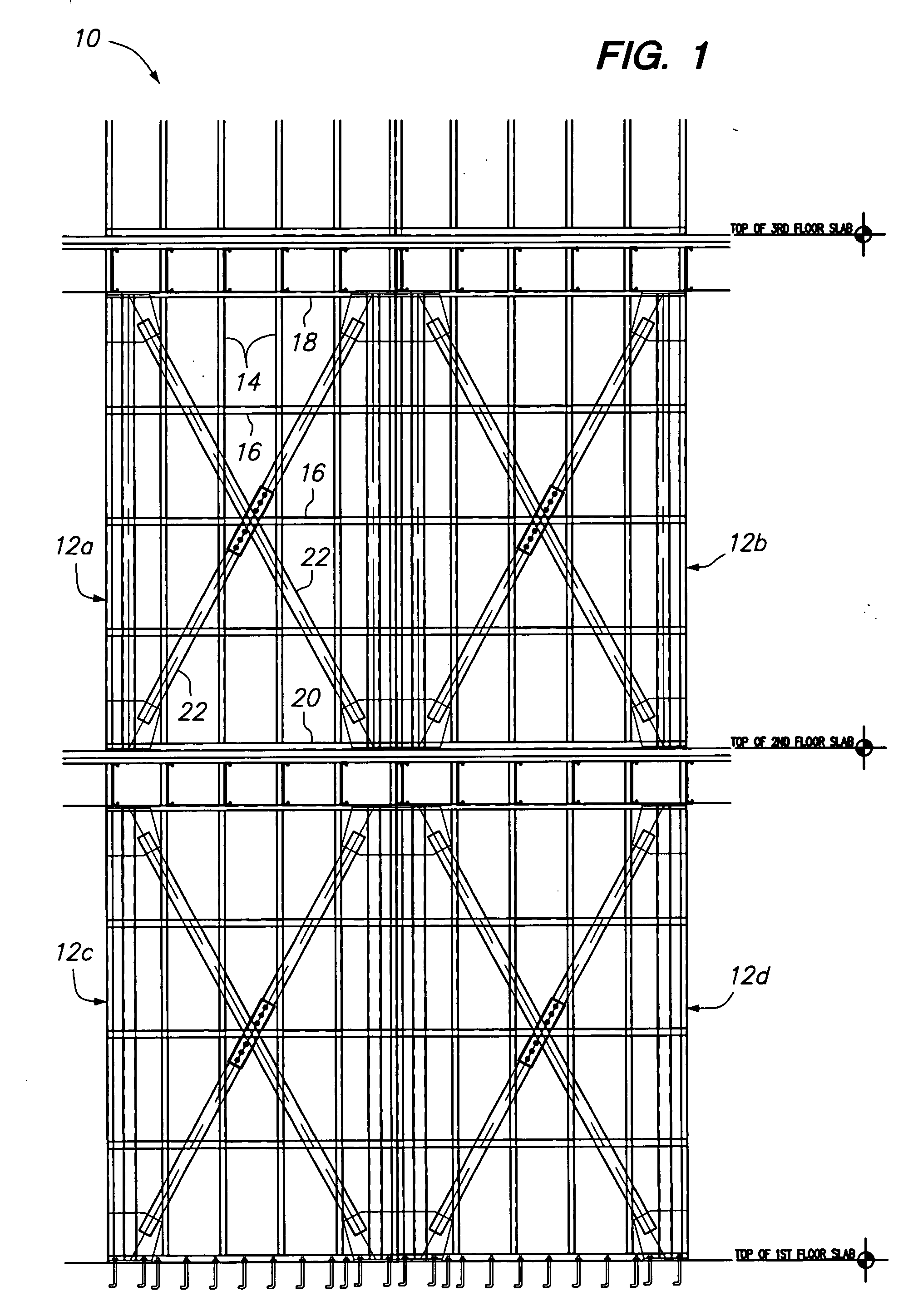
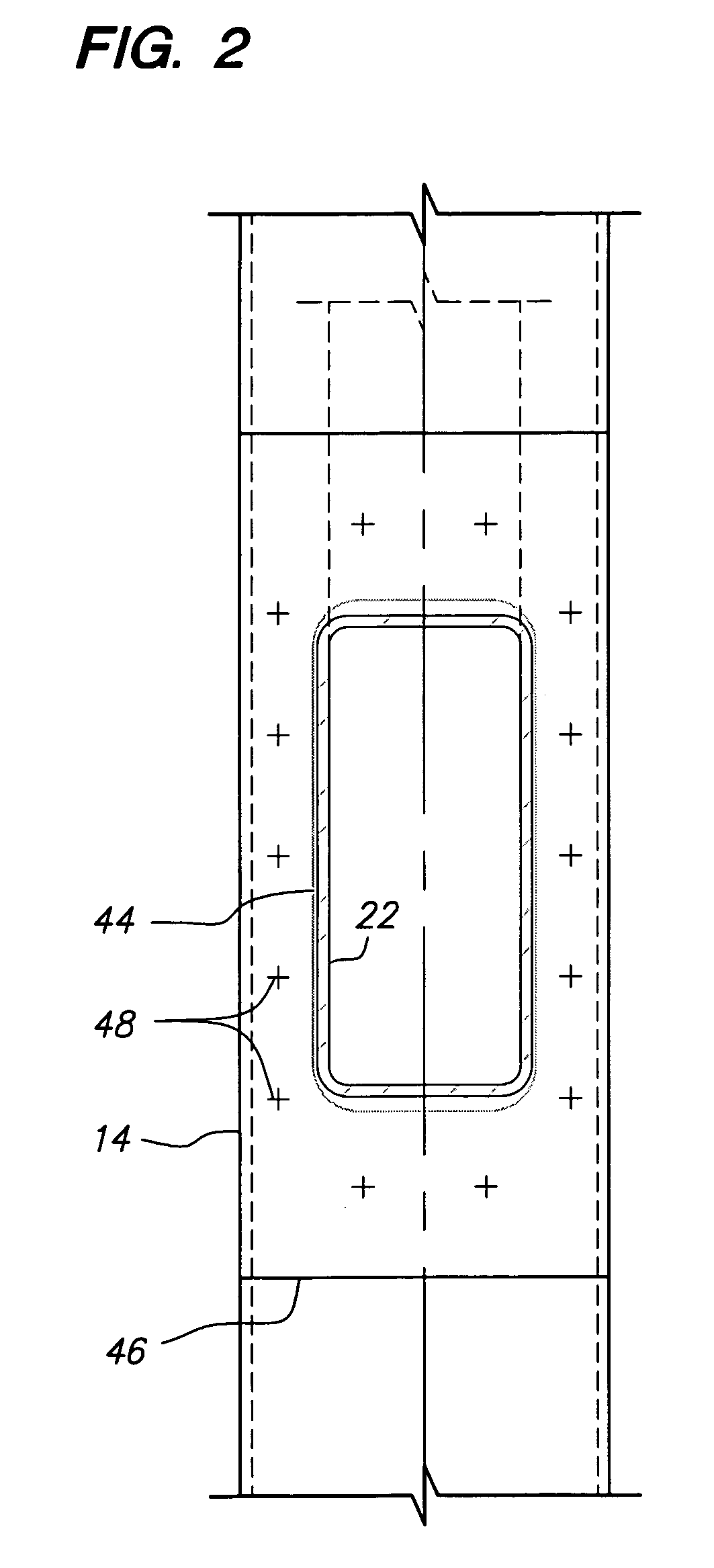
[0016] Referring now to the drawings wherein the showings are for purposes of illustrating preferred embodiments of the present invention only, and not for purposes of limiting the same, FIG. 1 is an elevation view of a wall 10 used in the construction of a building structure. The wall 10 is made from four panels 12a-12d. Each of the panels 12 is primarily fabricated from metal wall studs of light gage steel as is commonly known. The panels 12 can be constructed off-site and delivered to the building construction site for assembly. Referring to panel 12a, each of the panels 12 has vertical wall studs 14 and horizontal wall studs 16. The vertical wall studs 14 run continuously between a top plate 18 and a bottom plate 20 and are horizontally spaced about sixteen inches apart. The horizontal wall studs 16 are blocking members that are connected between adjacent vertical studs 12. The horizontal studs 16 are fabricated from the same light gage steel as the vertical studs 12 and are con...


PUM


Abstract

A metal panelized wall system having a plurality of generally parallel vertical wall studs with an opening formed in each one. A top horizontal member is connected to a top end of each of the vertical wall studs and a bottom horizontal member is connected to a bottom end of each of the vertical wall studs. Extending from the bottom horizontal member to the top horizontal member is at least one diagonal member. The diagonal member extends through the openings formed in the vertical wall studs such that loads from the vertical wall studs are not transferred to the diagonal member.

Description

FIELD OF THE INVENTION [0001] The present invention relates generally to construction techniques using metal wall studs and more particularly to providing diagonal “X” bracing to the wall. BACKGROUND OF THE INVENTION [0002] Metal wall studs are used in the construction industry to provide the framing members used for the construction of buildings. The metal wall studs are used instead of conventional wood framing members to form the wall panels. The panels can be pre-assembled and delivered to the building site where they are put in place. [0003] The typical wall panel consists of horizontal and vertical studs. In order to provide further reinforcement, diagonal wall members are placed between the corners of the panels. The diagonal members are needed to resist lateral loads to the wall panel and to comply with seismic building requirements. The diagonal members are straps that are typically connected to the face of the studs. In this arrangement, the diagonal members can only provi...

Claims


Application Information

Patent Timeline
Patent Type & Authority Applications(United States)
IPC IPC(8): E04B1/24E04B1/98E04C2/38E04C3/02E04C3/30E04H9/02E04H12/00
CPCE04B1/24E04B2001/2463E04H9/028E04C2/384E04B2001/2496E04H9/0237
Inventor MAJLESSI, KAMRAN REZA
Owner MAJLESSI KAMRAN REZA
Why Eureka
Try Eureka