Valve actuation controlling apparatus and method for engine

a valve actuation and controlling apparatus technology, applied in the direction of electric control, machines/engines, output power, etc., can solve the problems of inability to generate sufficient torque to counteract the increase in friction, and inability to ensure proper engine starting characteristics. , to achieve the effect of improving engine starting characteristics

Inactive Publication Date: 2005-10-20
TOYOTA JIDOSHA KK
View PDF0 Cites 26 Cited by
  • Summary
  • Abstract
  • Description
  • Claims
  • Application Information

AI Technical Summary

Benefits of technology

[0006] Accordingly, it is an objective of the present invention to provide valve act

Problems solved by technology

However, the above setting of the valve actuation of intake valves does not always ensure proper engine starting characteristics depending on engine starting conditions.
For example, during a very cold start in which engine parts encounter high friction, working angle θ that is less than that of idling may result in a shortage of intake air, making it impossible to generate sufficient torque to counteract the increased friction.
On the other hand

Method used


Image

  • Valve actuation controlling apparatus and method for engine
  • Valve actuation controlling apparatus and method for engine
  • Valve actuation controlling apparatus and method for engine

Examples


Embodiment Construction

[0025] An embodiment of the present invention will be described in detail below with reference to the drawings.

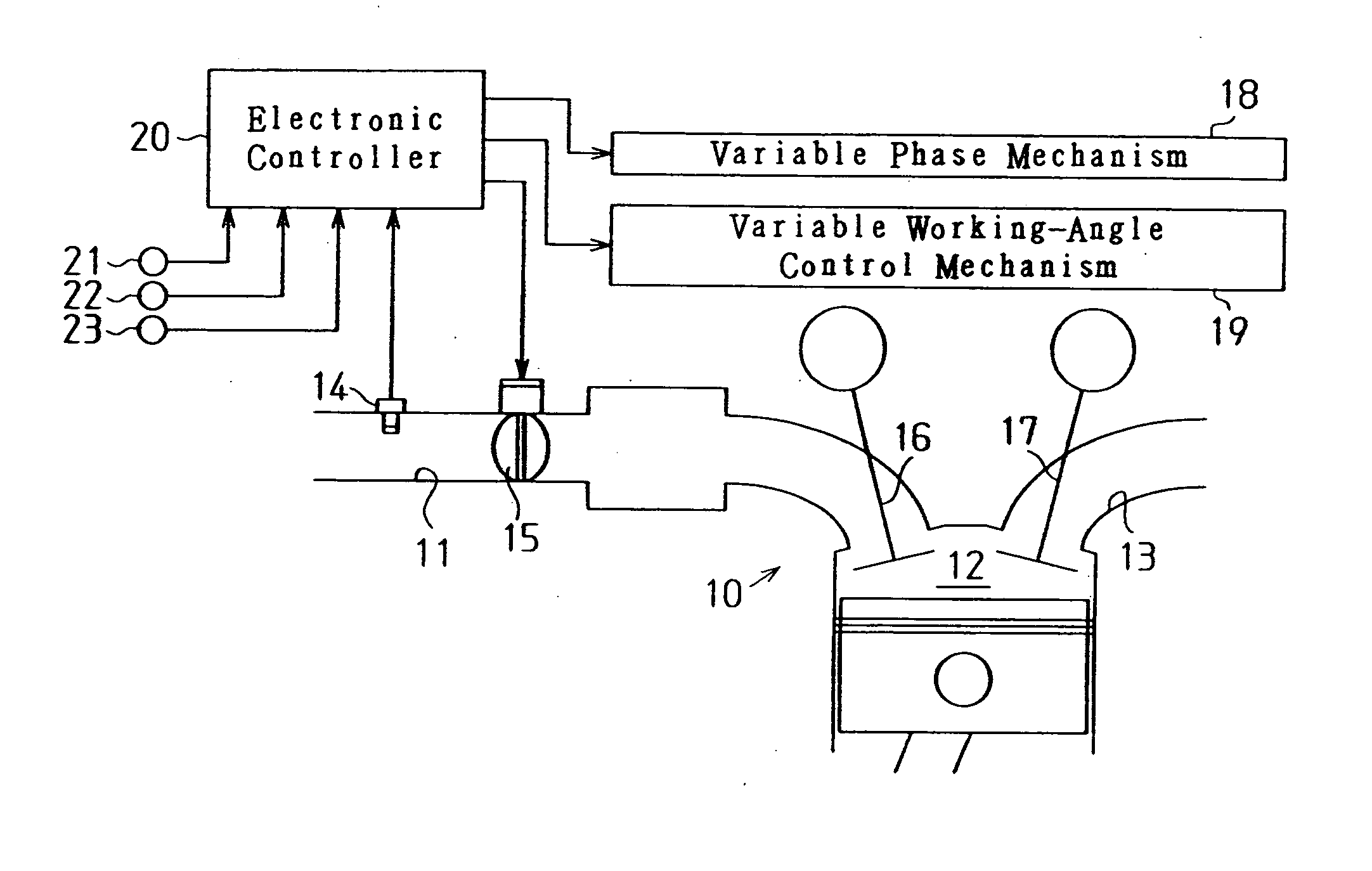
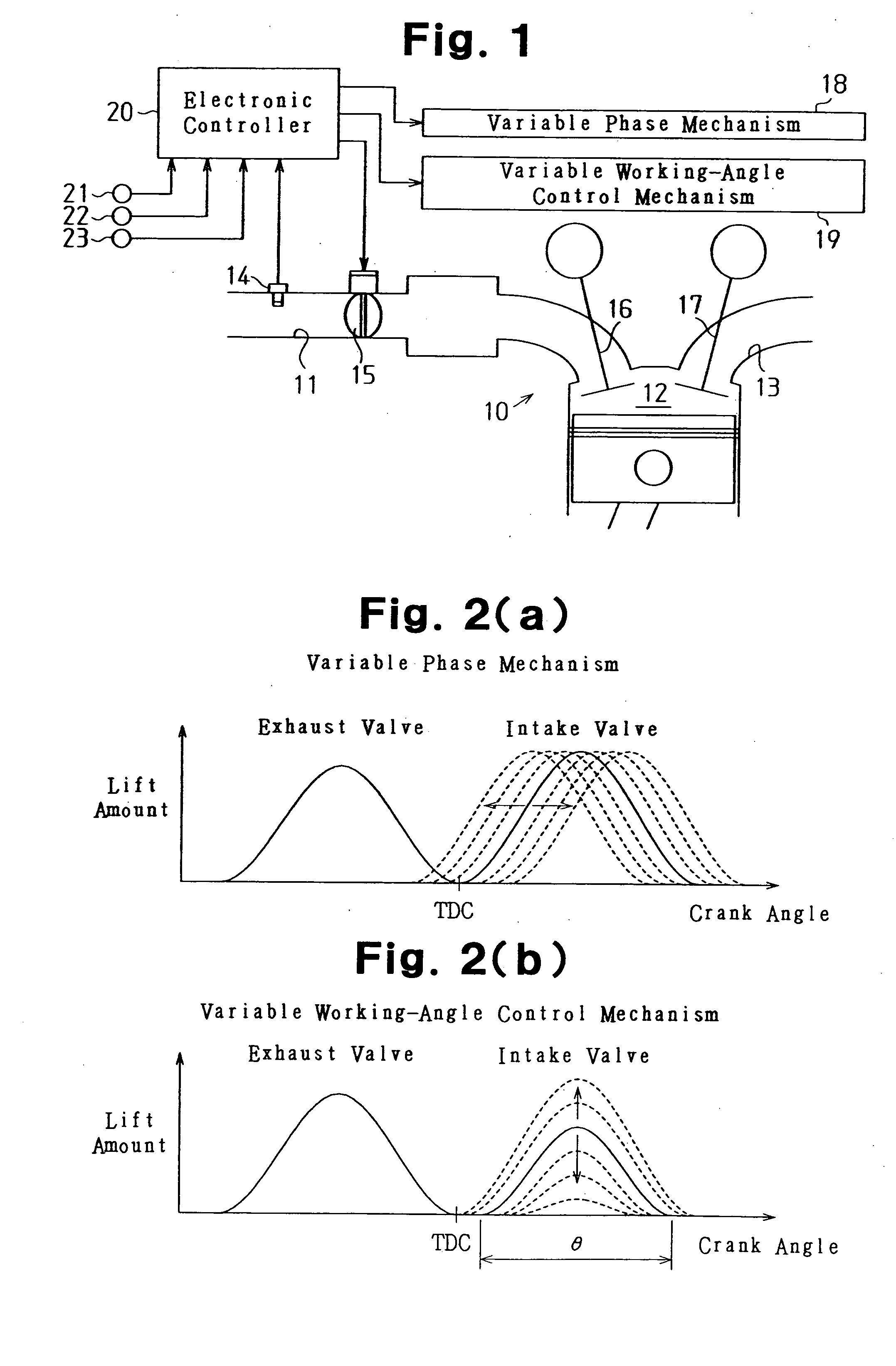
[0026] As shown in FIG. 1, an engine 10 includes an intake passage 11, a combustion chamber 12, and an exhaust passage 13. Installed in the intake passage 11 are an air flowmeter 14 which detects an air flow rate in the intake passage 11 and a throttle valve 15 which changes the air flow rate by changing the flow area of the intake passage 11. The intake passage 11 is connected to the combustion chamber 12 via an intake valve 16. The combustion chamber 12 is connected to the exhaust passage 13 via an exhaust valve 17. The intake valve 16 and exhaust valve 17 are driven according to rotation of the engine 10. The intake valve 16 opens and closes the intake passage 11 to the combustion chamber 12, and the exhaust valve 17 opens and closes the exhaust passage 13 to the combustion chamber 12.

[0027] A valve operating system of the intake valve 16 has a variable phase mechanism...


PUM


Abstract

After commanding an engine to stop, an electronic controller controls a variable working-angle control mechanism to increase the working angle of an intake valve in preparation for restarting of the engine. In the case of an automatic stop, which is followed by restarting of the engine in a relatively short time, the working angle of the intake valve is set to the maximum working angle of the variable working-angle control mechanism, which maximizing decompression. In a manual stop, it is necessary to allow for both hot start and cold start. Also, in the manual stop, a target working angle when the engine is stopped is set less than that of a case of the automatic stop. Thus, the starting characteristic is prevented from being degraded by increased friction of engine parts during a cold start, and knocking is prevented from occurring due to a high compression ratio in a cylinder during a hot start.

Description

BACKGROUND OF THE INVENTION [0001] The present invention relates to a valve actuation controlling apparatus and method applied to an engine equipped with a variable working-angle control mechanism which varies the working angle of intake valves. [0002] Engines such as vehicle engines are equipped with variable valve mechanisms which vary valve characteristics of intake valves and exhaust valves. Among variable valve mechanisms proposed recently, there are variable valve lift and working-angle control mechanisms which vary valve lifts and working angles of intake and exhaust valves. [0003] Japanese Laid-Open Patent Publications No. 2002-89303 and No. 2002-61522 each disclose a valve actuation controlling apparatus that presets the valve actuation of intake valves to be suitable for securing engine starting characteristics immediately before the engine stops, thereby preparing for a next engine start. As shown in FIG. 8, immediately before the engine stops, that is after commanding th...

Claims


Application Information

Patent Timeline
IPC IPC(8): F01L1/34F01L13/00F02D13/02F02D17/00F02D29/02F02D41/04F02D45/00
CPCF01L1/34F01L13/00F01L2800/03F02D13/0234Y02T10/18F02D41/042F02D2041/001Y02T10/42F02D41/0005Y02T10/12Y02T10/40
Inventor HASHIZUME, AKIRA
Owner TOYOTA JIDOSHA KK
Why Eureka
Try Eureka