Treatment method for improving fatigue life and long-life metal material treated by using same treatment

Inactive Publication Date: 2005-10-20
NIPPON STEEL CORP
View PDF9 Cites 25 Cited by
  • Summary
  • Abstract
  • Description
  • Claims
  • Application Information

AI Technical Summary

Benefits of technology

[0027] In accordance with a sixteenth aspect of the invention, a treatment method is provided, wherein, in the quality assurance examination according to the first aspect above, paint is coated such that, when a crack occurs during subsequent usage in the ultrasonic impact treated portion after passing the quality assurance examination, a micro-capsule contained within the painted film is broken at the crac

Problems solved by technology

In practice, however, when there is a minute flaw in the spot likely to be affected by fatigue, it may degrade the fatigue strength.
Therefore, in order to be effective, the grinding treatment requires high skill and the execution of the treatment work may require much time.
These factors result in a considerable increase in the cost.
This is also a considerable cost factor.
On the other hand, in those methods which aim to introduce compressive residual stress, the compressive residual stress is not visible to the naked eye, and the effect of the treatment is difficult to measure and cannot be readily assured by inspection.
Thus, in view of quality control, this type of treatment is usually not adopted unless an engineer competent in diagnosis and judgement can attend to the treatment work at the site.
A surface flaw that is produced at the time of treatment, however, may bring about stress concentration and result in degradation of fatigue strength.
In addition, as workability is poor due to the large reaction produced when the plastic deformation is imparted, fine control is difficult and quality control becomes very difficult.
Especially when the treatment method for improving fatigue characteristics by introducing compressive residual stress as described above is applied, if there are cracks of 1 mm or less in length, which represent an early stage of occurrence of fatigue cracks a

Method used


Image

  • Treatment method for improving fatigue life and long-life metal material treated by using same treatment
  • Treatment method for improving fatigue life and long-life metal material treated by using same treatment
  • Treatment method for improving fatigue life and long-life metal material treated by using same treatment

Examples


Example

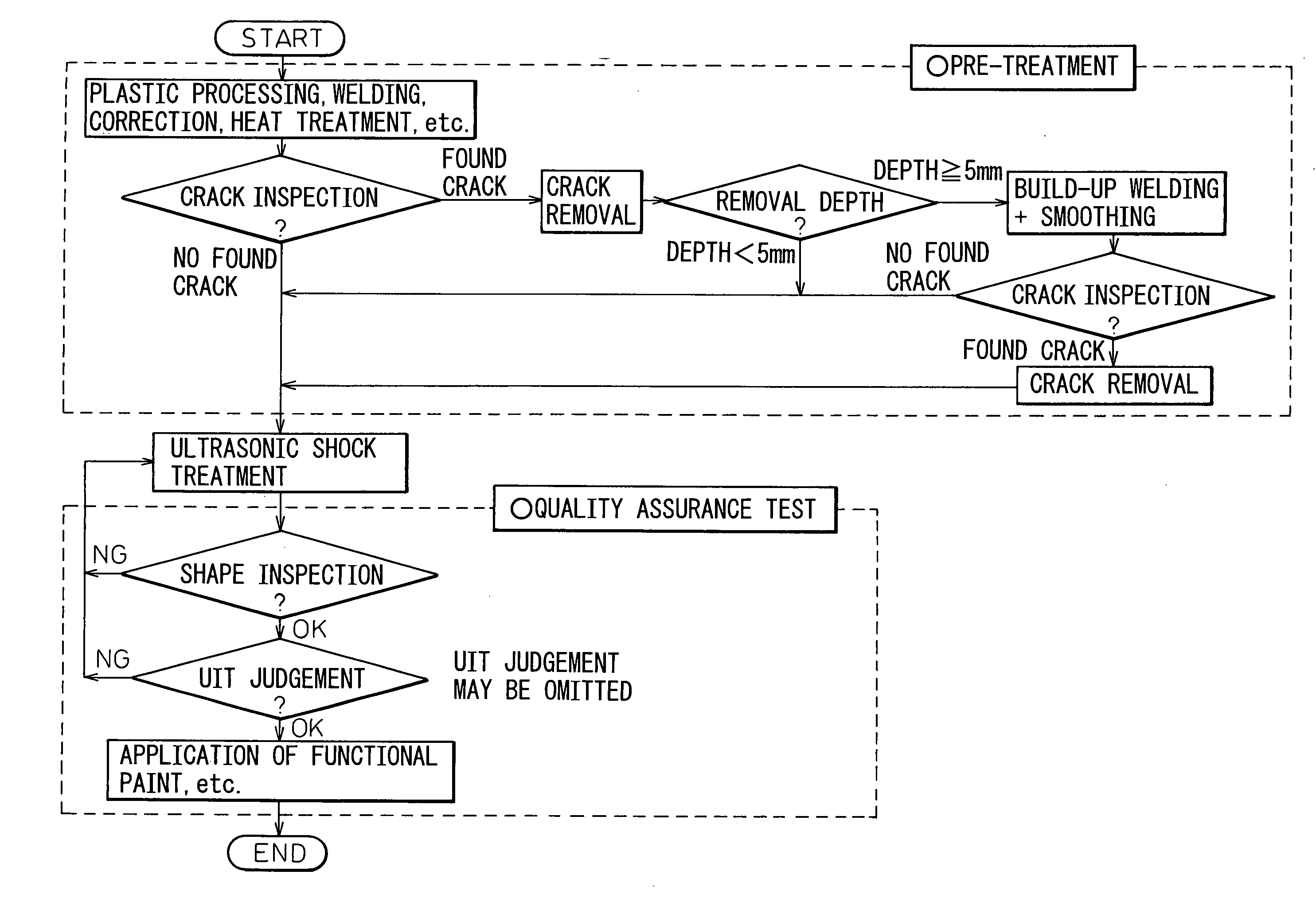
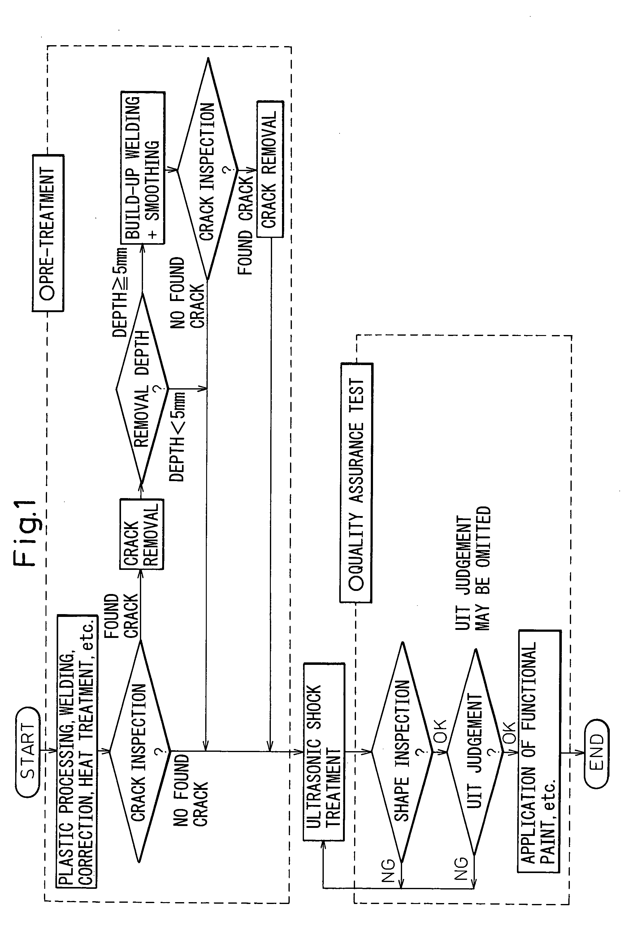
[0033] Occurrence of fatigue fracture in metal is greatly influenced by stress concentration and residual stress. When a metal material is subjected to load, dislocations tend to accumulate at the point of stress concentration, and as a result, slip lines accumulate there and develop into a crack, and the crack develops and propagates after it is produced. Residual stress is usually present as tensile residual stress at welded portion or the like, and is considered to enlarge the range of repeated stress and help to give rise to a crack as well as to promote opening of the produced crack. Therefore, in order to improve fatigue life of a metal material, it is necessary to relieve the stress concentration and to realize compressive residual stress as far as possible.

[0034] A welded point of a metal material contains both sharp change in surface shape and tensile residual stress, and therefore, constitutes the weakest point with respect to fatigue strength. The sharp change in surface...


PUM

PropertyMeasurementUnit
Fractionaaaaaaaaaa
Fractionaaaaaaaaaa
Lengthaaaaaaaaaa

Abstract

A novel treatment method, for improving fatigue life, is provided that aims to resolve problems associated with conventional treatment methods for improving fatigue life of metal by reduction of stress concentration and conventional treatment methods for improving fatigue life of metal by introduction of compressive stress, that is, problems of poor efficiency in work execution, required level of skill of workers, and the impossibility of quality control due to lack of means for measuring the effect after treatment, characterized in that, for locations in metal for which fatigue is a problem, after pre-treatment is performed, ultrasonic impact treatment is performed, and thereafter, a quality assurance test is performed so as to improve the fatigue life of the metal.

Description

TECHNICAL FIELD OF THE INVENTION [0001] The present invention relates to metal products such as large welded structures, e.g. a bridge, etc., welded metal products, e.g. a base carrier of an automobile, etc., non-welded metal products such as a vehicle wheel, etc. and, more particularly, to a treatment method for improving fatigue life that increases durability, with respect to fatigue crack, and especially in locations likely to be impaired by fatigue, in order to permit the useful life to be lengthened, and to a metal material treated by using same treatment method. DESCRIPTION OF THE BACKGROUND ART [0002] The durability of a metal product is often determined by the fatigue strength of the product. In order to increase the fatigue strength, a general practice is to increase the design cross-section to thereby reduce stress. However, various other treatment methods may be employed to improve fatigue characteristics. [0003] Treatment methods for improving fatigue characteristics may...

Claims


Application Information

Patent Timeline
IPC IPC(8): C21D10/00G01N27/90
CPCG01N27/90C21D10/005C21D10/00
Inventor TOMINAGA, TOMONORIMATSUOKA, KAZUMIISHIKAWA, TADASHIKASUYA, TADASHIHOMMA, KOJI
Owner NIPPON STEEL CORP
Why Eureka
Try Eureka