
Thermal interface material and method for manufacturing same

a technology of thermal grease and interface materials, which is applied in the direction of electrical apparatus construction details, lighting and heating apparatus, electrical apparatus casings/cabinets/drawers, etc., can solve the problem of reducing the heat conducting efficiency of thermal grease, reducing the relative amount of resin mixture, and unable to efficiently transmit heat produced in electronic components to the heat dissipating device. , to achieve the effect of excellent heat conduction

Inactive Publication Date: 2005-10-20
HON HAI PRECISION IND CO LTD
View PDF14 Cites 20 Cited by
  • Summary
  • Abstract
  • Description
  • Claims
  • Application Information

AI Technical Summary

Benefits of technology

[0011] Accordingly, an object of the present invention is to provide a thermal interface material having excellent heat conduction.
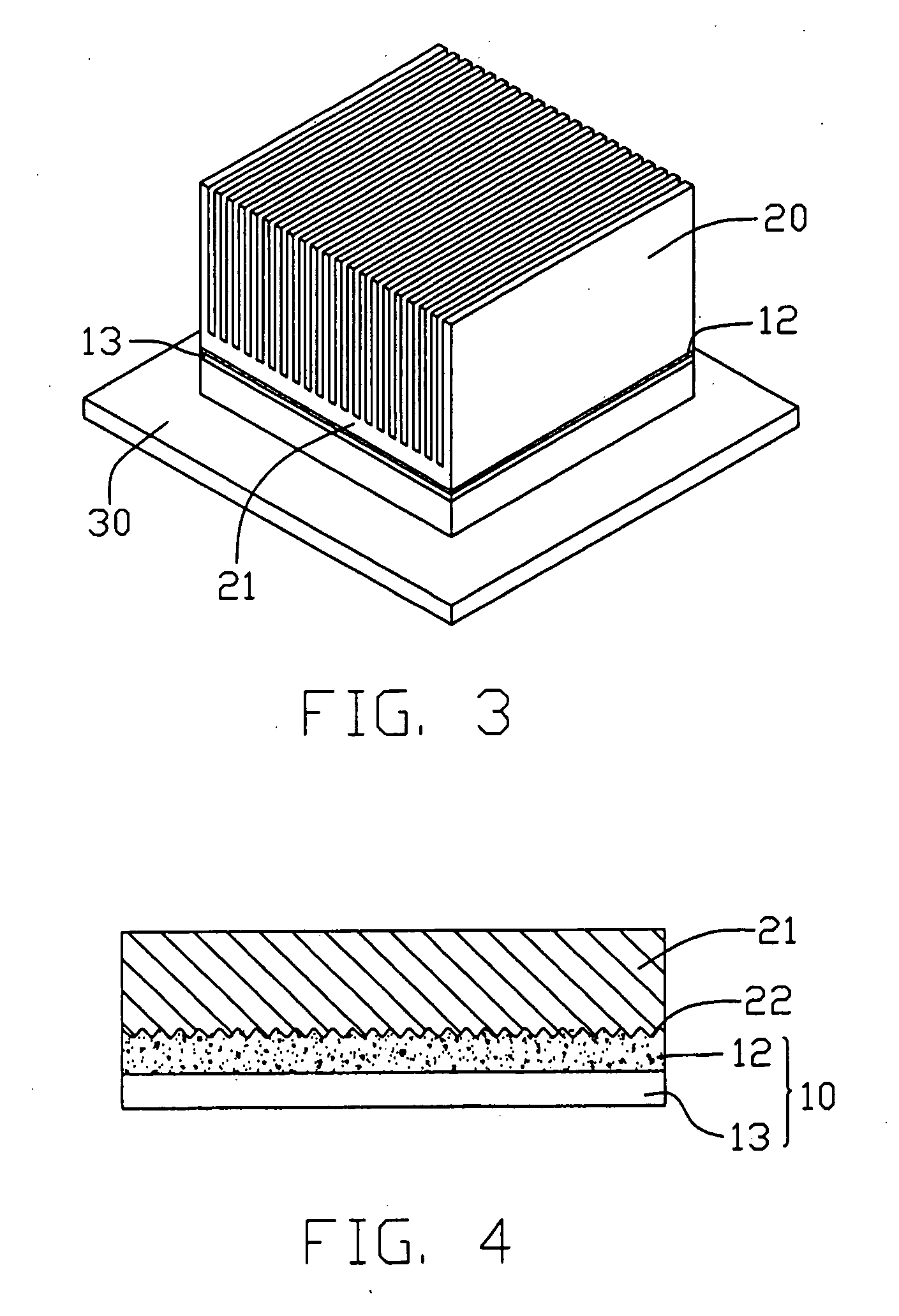
[0018] Unlike in a conventional thermal interface material, the thermal interface material of the present invention comprises the film composed of the shape memory alloy, the shape memory alloy comprising one or more nano-alloys. Thus the thermal interface material has the Shape Memory Effect, and can have a large surface area. The shape memory alloy is deposited on and compactly engages with the base of the dissipating device at the operating temperature of the heat source. In use, the temperature of the thermal interface material rises to the operating temperature, and the film recovers its original shape and can engage with the base compactly. This ensures excellent contact between the thermal interface material and the heat dissipating device. Thus the thermal interface material provides an excellent thermal path between the electronic device and the heat dissipating device.

Problems solved by technology

Therefore, the heat produced in the electronic component cannot be efficiently transmitted to the heat dissipating device for dissipation to the external environment.
This results in incomplete contact between the heat dissipating device and the thermal grease, thus reducing the heat conducting efficiency of the thermal grease.
However, in the above-described thermal interface material, the relative amount of the resin mixture is very small.
Thus the resin mixture has a low viscosity, and cannot efficiently retain the filler therein.
This reduces the heat conducting efficiency and performance of the thermal interface material.

Method used


Image

  • Thermal interface material and method for manufacturing same
  • Thermal interface material and method for manufacturing same
  • Thermal interface material and method for manufacturing same

Examples


Embodiment Construction

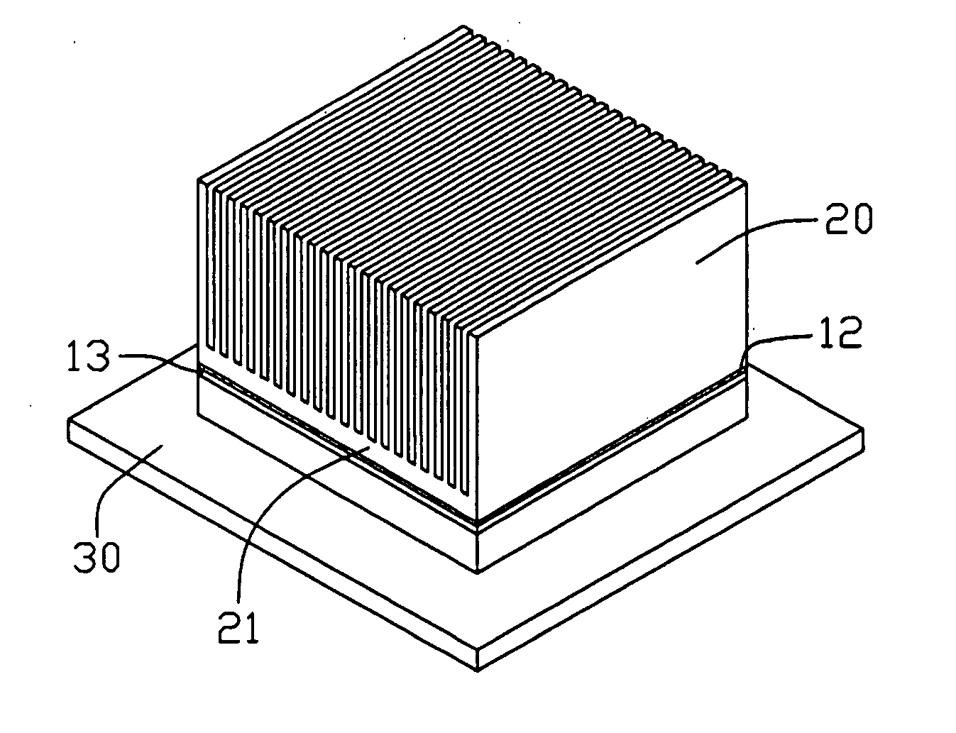
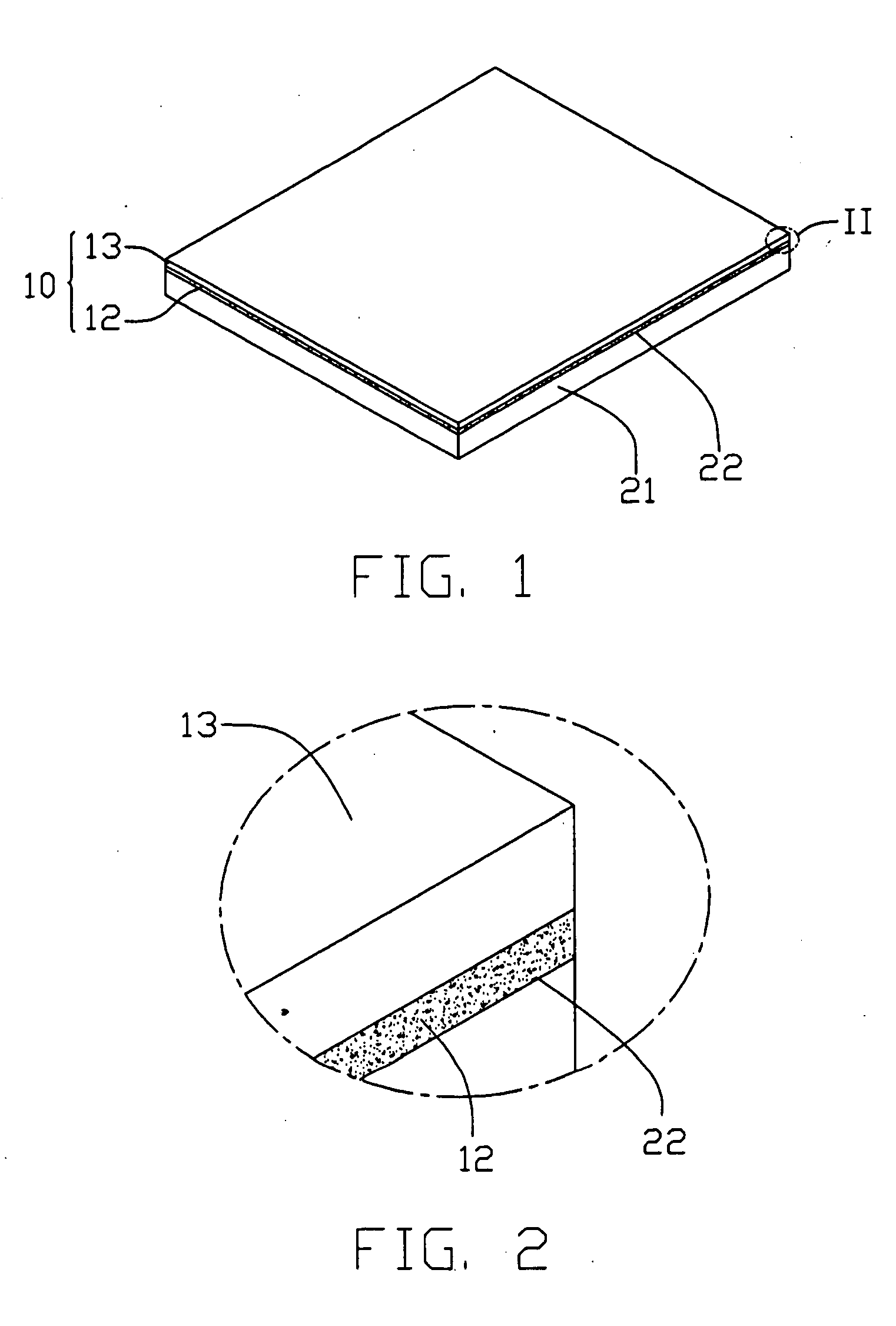
[0027] Referring to FIG. 1, a thermal interface material 10 formed on a surface 22 of a base 21 is shown. Referring also to FIG. 3, the base 21 is a portion of a heat sink 20. The thermal interface material 10 comprises a shape memory effect thin film 12, and a thermal grease 13 attached on the film 12. The film 12 is composed of a shape memory alloy, and is formed on the surface 22 of the base 21 by vacuum sputtering deposition at an operating temperature of an electronic device 30. The electronic device 30 is a heat-generating component such as a computer chip. The film 12 engages with the base 21 compactly. The shape memory alloy is a nano-alloy selected from the group consisting of a nano-NiTiCu alloy, a nano-CuAlNi alloy, a nano-CuAlZn alloy, a nano-NiTiAlCu alloy, a nano-NiTiAlZn alloy, and a nano-NiTiAlZnCu alloy. In the preferred embodiment, the shape memory alloy is a nano-NiTiCu alloy. The above-mentioned nano-alloys have high thermal interface conductivities. Diameter of ...


PUM


Abstract

A thermal interface material (10) includes a shape memory effect thin film (12), and a thermal grease (13) attached on the film. The film is composed of a shape memory alloy, and is formed on a base (21) of a heat sink (20) at an operating temperature of a heat-generating electronic device (30). This is done by vacuum sputtering deposition or a like process. The shape memory alloy is a nano-NiTiCu alloy or a like alloy. In use, the thermal interface material enhances the thermal contact between the electronic device and the heat sink. A method for manufacturing the thermal interface material includes: (a) providing a base which is a portion of a heat sink; (b) depositing a film of a shape memory alloy on a surface of the base at an operating temperature of a heat source and under vacuum; and (c) applying a thermal grease on the film.

Description

BACKGROUND OF THE INVENTION [0001] 1. Field of the Invention [0002] The invention relates generally to thermal interface materials and manufacturing methods thereof; and more particularly to a kind of thermal interface material which enhances contact between a heat source and a heat dissipating device, and a manufacturing method thereof. [0003] 2. Description of Related Art [0004] Electronic components such as semiconductor chips are becoming progressively smaller, and the operating speeds thereof are becoming progressively higher. Correspondingly, the heat dissipation requirements of these components are increasing too. In many contemporary applications, a heat dissipating device is fixed on or near the electronic component to dissipate heat therefrom. Generally, however, there is a clearance between the heat dissipating device and the electronic component. The heat dissipating device does not engage with the electronic component compactly. Therefore, the heat produced in the elect...

Claims


Application Information

Patent Timeline
IPC IPC(8): H01L23/373H01L23/42H05K5/00H05K7/20
CPCH05K5/0021
Inventor CHEN, GA-LANE
Owner HON HAI PRECISION IND CO LTD
Learn More