Thin-diameter coaxial cable and method of producing the same

a coaxial cable, thin-diameter technology, applied in the direction of cables, insulated conductors, waveguides, etc., can solve the problems of adversely affecting the electrical characteristics of the coaxial cable, the variation of high-frequency characteristics and electrical characteristics, and the difficulty of ensuring extrusion stability, so as to improve the geometric accuracy, increase the size of the resin discharge portion of the die, and increase the molding rate

Inactive Publication Date: 2005-10-20
UBE NITTO KASEI CO LTD
View PDF2 Cites 74 Cited by
  • Summary
  • Abstract
  • Description
  • Claims
  • Application Information

AI Technical Summary

Benefits of technology

[0034] With this configuration, unlike the invention described in claim 13, the coupling portions and the outer annular portion are integrated and molded with a draft. In the process, the draft makes it possible to increase the size of the resin discharge portion of the die as c

Problems solved by technology

In the case of the foaming extrusion technique, however, it is difficult to secure the extrusion stability.
Especially, in the extrusion of a small-diameter component, the outer diameter of the insulated covering layer undergoes a delicate change, thereby causing the variation in the high-frequency characteristic and the electrical characteristics.
In

Method used


Image

  • Thin-diameter coaxial cable and method of producing the same
  • Thin-diameter coaxial cable and method of producing the same
  • Thin-diameter coaxial cable and method of producing the same

Examples


specific example 1

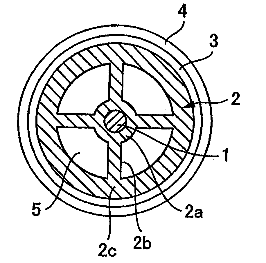
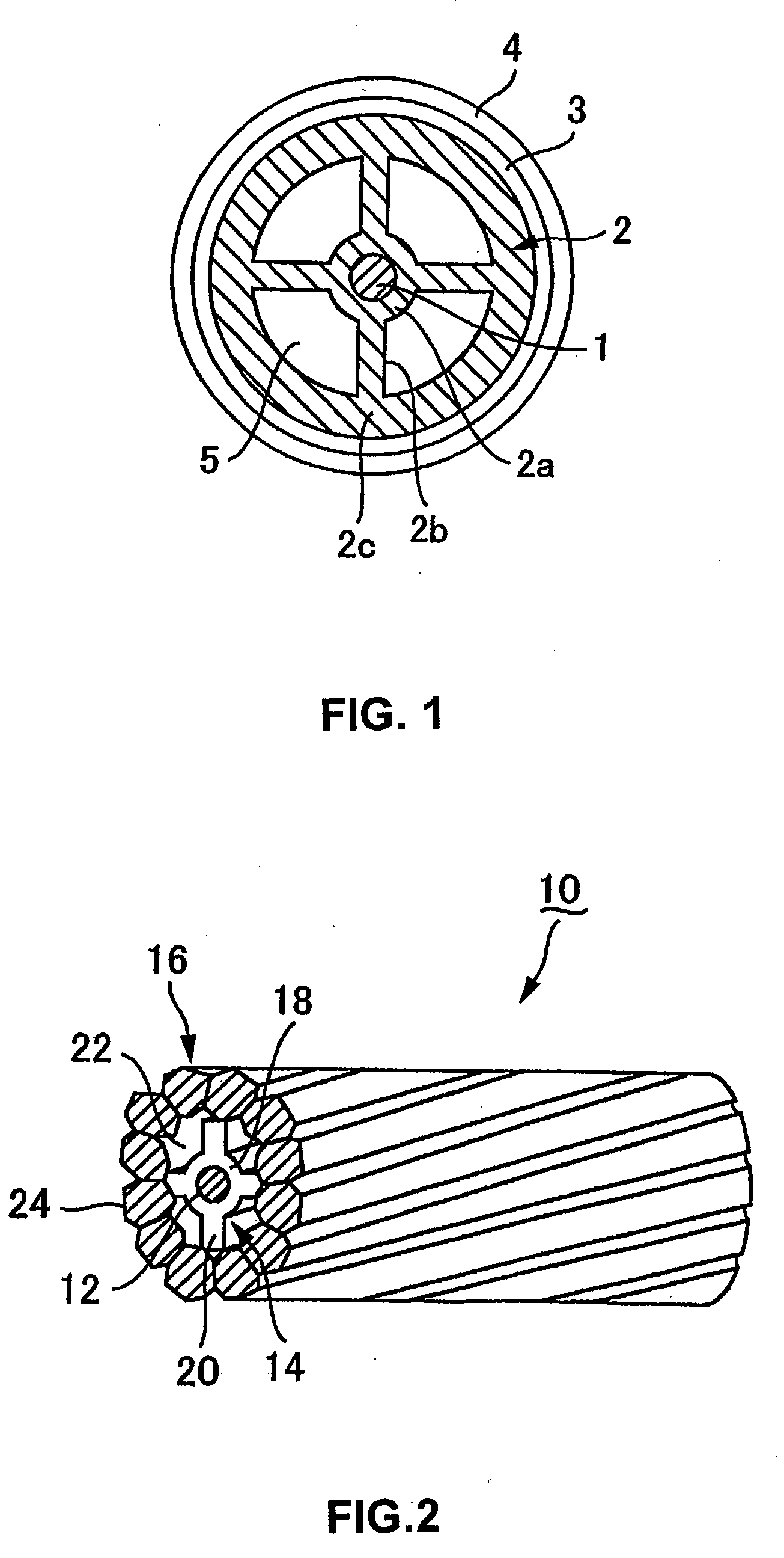
[0088] The central conductor (silver-plated copper wire having the outer diameter φ of 0.1 mm) 1 was heated, so that the surface temperature became 100° C., by a heater using an electric burner, introduced to a cross head die and inserted through a covering die (nozzle) 30 having the shape shown in FIG. 7.

[0089] The covering die 30 shown in FIG. 7 includes a central hole 30a for inserting the central conductor 1 therethrough, and four radial split holes (resin discharge holes) 30b formed on the outer peripheral edge of the central hole 30a and extending radially outward.

[0090] The inner diameter of the central hole 30a is larger than the outer diameter of the central conductor 1, and once the central conductor 1 was inserted through the central hole 30a, predetermined gaps (resin discharge portions) were formed between the outer periphery of the conductor 1 and the central hole 30a and the resin is discharged into these gaps.

[0091] Also, the four slit holes 30b had substantially ...

specific example 2

[0102] The central conductor (silver-plated copper wire having an outer diameter φ of 0.1 mm) was heated so that the surface temperature became 100° C. by a heater using an electric burner, and then introduced to a cross head die. The central conductor 1, while being inserted through the central hole 30a as in the first specific example, was taken off at the rate of 30 m / min. At the same time, FEP (trade name NP-100 of Daikin Kogyo Co., Ltd.) having a relative dielectric constant of 2.1 was covered by being extruded at the extrusion temperature of 350° C., with a draft, from the resin discharge portions defined by the periphery of the central holes 30a and the slit holes 30b. In this way, a generally cross-shaped intermediate molded component 40 shown in FIG. 8 was obtained.

[0103] Next, the intermediate molded component 40 thus obtained was introduced to a circular pipe covering die and covered by extrusion in annular fashion with cyclic polyolefin (trade name ZEONEX RS820 of ZEON ...

specific example 3

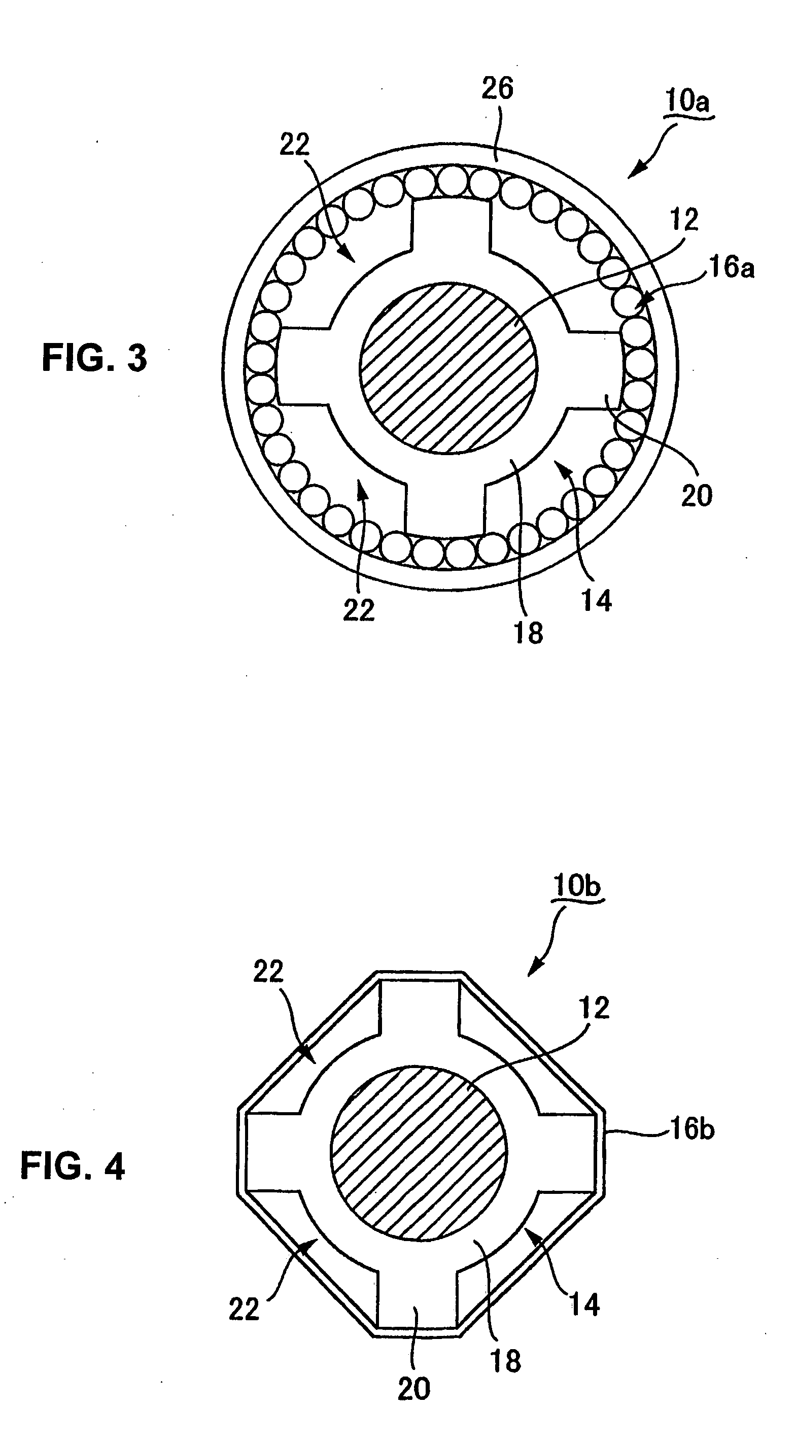
[0107] The central conductor (silver-plated copper wire having the outer diameter φ of 0.1 mm) 1 was heated so that the surface temperature became 100° C. by a heater using an electric burner, introduced to a cross head die and inserted into a covering die (nozzle) 60 in the shape shown in FIG. 10.

[0108] The die 60 shown in FIG. 10 includes a central hole 60a for inserting the central conductor 1 therethrough, and four split holes 60b formed adjacently to each other on the outer periphery of the central hole 60a. The inner diameter of the central hole 60a is larger than the outer diameter of the central conductor 1.

[0109] The four split holes 60b have substantially the same shape and are arranged equidistantly along the peripheral direction around the center hole 60a. These generally T-shaped split holes 60b each include an arcuate portion and a base formed from the center of the arcuate portion.

[0110] The edge of the base of each T-shaped split hole 60b is arranged in proximity ...


PUM


Abstract

A small-diameter coaxial cable comprises a central conductor, an insulated covering layer arranged on the outer periphery of the central conductor and having air gaps continuous along the longitudinal direction and an outer conductor layer arranged on the outer periphery of the insulated covering layer. The insulated covering layer includes an inner annular portion covering the outer periphery of the central conductor, a plurality of coupling portions extending outward from the inner annular portion and an outer annular portion connecting the outer peripheral edges of the coupling portions to each other. Air gaps defined along the peripheral direction by the coupling portions are formed on the inner side of the insulated covering layer.

Description

TECHNICAL FIELD [0001] The present invention relates to a small-diameter coaxial cable being superior in high-frequency characteristic and electrical characteristics and a method of fabricating the same. BACKGROUND ART [0002] With the recent trend toward an increased information volume and an increased transmission speed, the coaxial cable has begun to be used for the antenna wire of the portable information terminals and the wires connecting the LCD and the CPU. On the other hand, the reduced size and thickness of the information terminals and notebook-sized personal computers requires a smaller diameter of the coaxial cable. Generally, to acquire the coaxial cable having superior electrical characteristics, it is crucial to decrease the dielectric constant of an insulated covering layer formed on the outer periphery of the central conductor as much as possible. For this purpose, the insulated covering layer is often formed of fluoro resin or polyolefin resin which is low in dielec...

Claims


Application Information

Patent Timeline
IPC IPC(8): H01B11/18
CPCH01B11/1834
Inventor ISHII, TOKUMATSUNO, SHIGEHIROWATANABE, KAZUNORITANAKA, SEIJI
Owner UBE NITTO KASEI CO LTD
Why Eureka
Try Eureka