Watershed runoff drainage device & method
- Summary
- Abstract
- Description
- Claims
- Application Information
AI Technical Summary
Benefits of technology
Problems solved by technology
Method used
Image
Examples
embodiment a
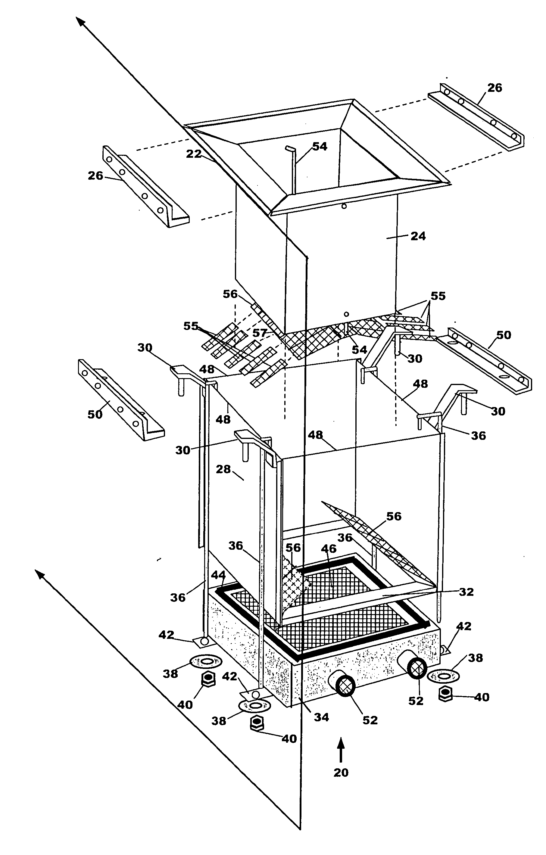
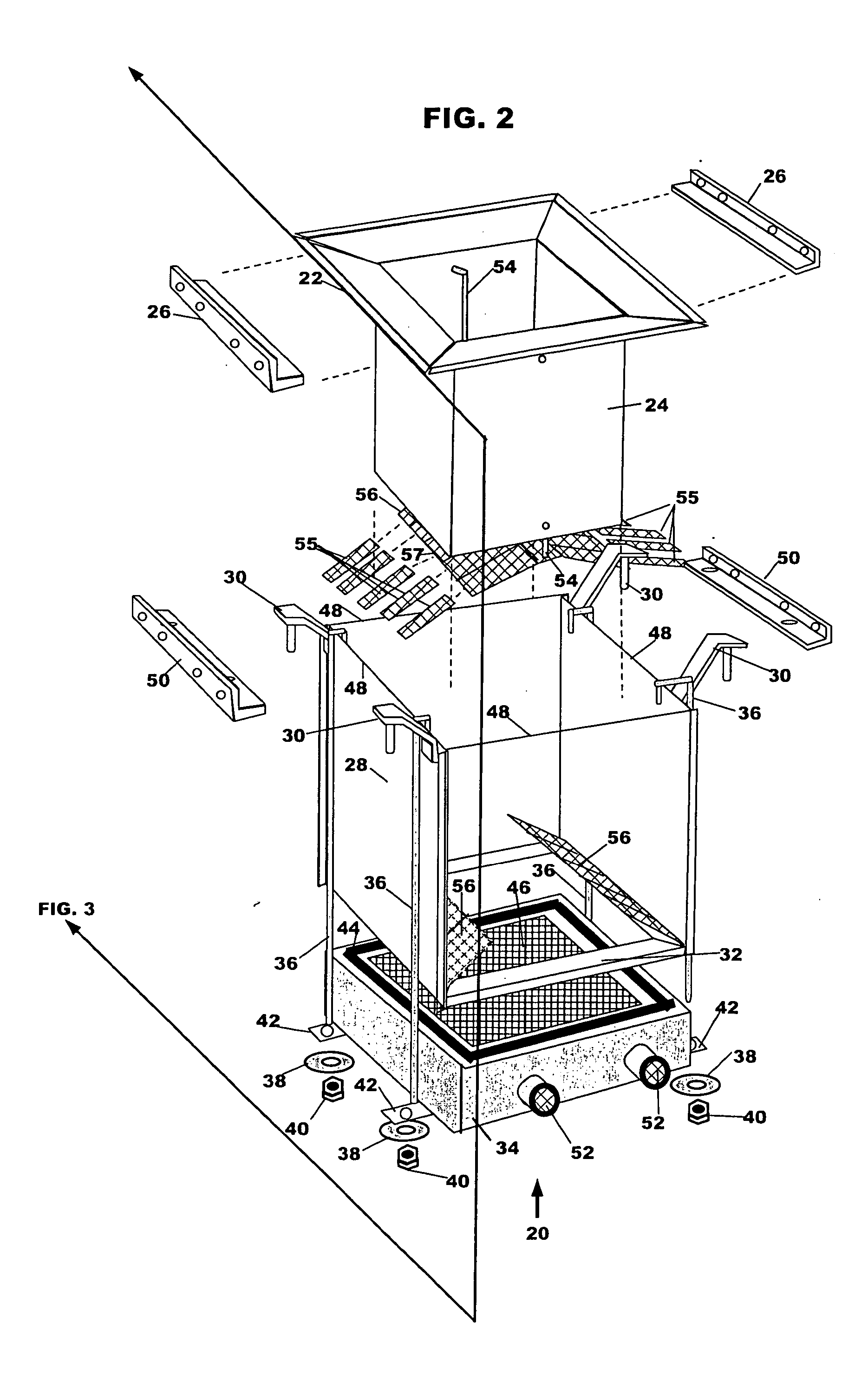
[0061] Referring to FIGS. 2 and 3, there is disclosed one embodiment of this invention, the watershed runoff drainage device 20.
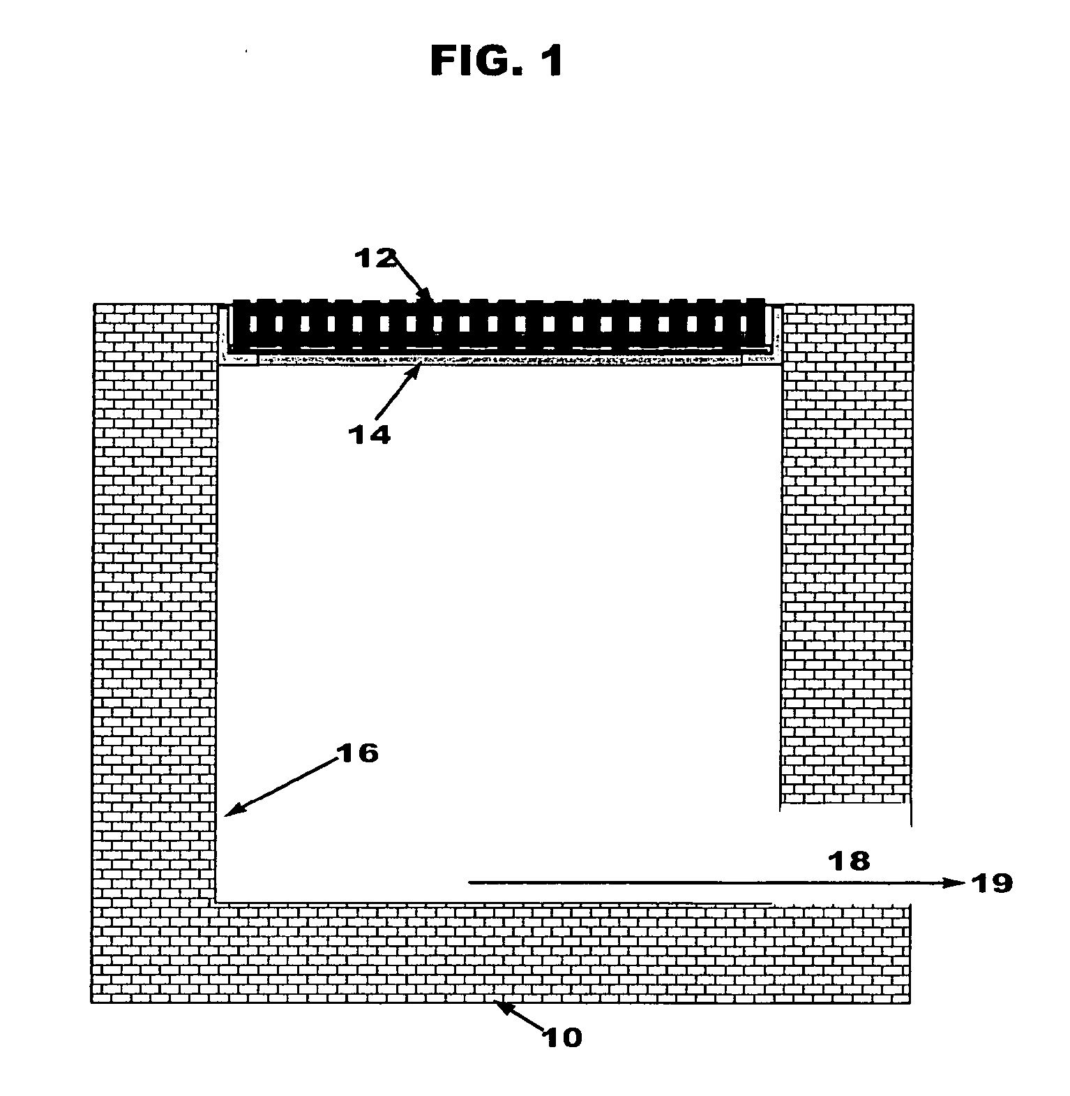
[0062] This device 20 may be installed in a typical rectangular configured top-entry bottom exit drain inlet vault 10 (FIG. 1). The vault 10 has a top-entry grate 12 through which storm water runoff from the surrounding watershed enters the inlet vault 10. Steel or cast iron rails 14 support the grating 12 above a vault interior 16 in which the storm water runoff would normally accumulate and flow without pre-treatment to the storm drain system via a bottom-exit pipe 18 to vault discharge 19. Such inlet vault s 10 may be made of concrete, steel, fiberglass, plastic or other non-permeable material.
[0063] As shown in FIG. 2 the watershed runoff drainage device 20 of this invention including the stainless steel (SS) or formed plastic funnel sub-assembly 21 comprised of an SS or formed plastic funnel 22 connected to an SS or formed plastic throat 24, SS rods ...
embodiment b
[0068] Another embodiment of this invention illustrated in FIGS. 5 and 6 is the watershed runoff drainage device 60. This device 60 includes the funnel sub-assembly 21, an additional permeable weir sub-assembly 61 described in detail below, a horizontal permeable weir filter element 62, and a vertical permeable weir filter element 63. Both filter elements 62 and 63 are removably inserted into elements of the permeable weir sub-assembly 61, plus deflector plates 23 selectively attached to the throat 240D and to the vault interior 16, ready for installation into a rectangular top-entry bottom-exit drain inlet vault 10. The deflector plates 23 serve two purposes, they slow and deflect rising liquid slowing the liquid velocity and increasing the fraction of settled solids and they serve as barriers to the vertical movement of the larvae and pupae mosquito stages, reducing their survival.
[0069] The permeable weir sub-assembly 61 comprises a welded SS angle frame 64 further welded to thr...
embodiment c
[0072]FIG. 7 illustrates another embodiment of this invention, the device 70 of this invention. This device 70 comprises the funnel sub-assembly 21 and an ADDS device 34 specially wall mounted to enable drain-down and spill control in top-entry bottom-exit drain inlet vaults which are not large enough to accommodate installation of the device 20. The special wall mounting ADDS support method comprises an SS angle frame 71 welded or otherwise connected and sized to enable the outer horizontal flange element of the SS angle frame 71 to reach within a fraction of an inch of the three vault interior walls 16 adjacent and opposite the pipe wall, and be positioned on top of three SS angle mounting brackets 72. Each has its top surface largely covered by a rubber or plastic seal 73, while the inner horizontal flange element of the SS angle frame 71 is recessed to allow the ADDS device 34 to nest inside the SS angle frame 71 once the upper surface of the inner horizontal flange element has ...
PUM
| Property | Measurement | Unit |
|---|---|---|
| Time | aaaaa | aaaaa |
| Angle | aaaaa | aaaaa |
| Flow rate | aaaaa | aaaaa |
Abstract
Description
Claims
Application Information
 - R&D
- Intellectual Property
- Life Sciences
- Materials
- Tech Scout
- Unparalleled Data Quality
- Higher Quality Content
- 60% Fewer Hallucinations
Browse by: Latest US Patents, China's latest patents, Technical Efficacy Thesaurus, Application Domain, Technology Topic, Popular Technical Reports.
© 2025 PatSnap. All rights reserved.Legal|Privacy policy|Modern Slavery Act Transparency Statement|Sitemap|About US| Contact US: help@patsnap.com


