Method and apparatus for determining depth of interactions in a detector for three-dimensional complete body screening

a detector and complete body technology, applied in the field of radiation detectors, can solve problems such as sticking differences between disciplines, and achieve the effect of efficient and cost-effective, clear and accurate imaging

Inactive Publication Date: 2005-10-20
CROSETTO DARIO B
View PDF0 Cites 8 Cited by
  • Summary
  • Abstract
  • Description
  • Claims
  • Application Information

AI Technical Summary

Benefits of technology

[0020] The present invention is directed to a system and method for efficiently and cost effectively determining an accurate depth of interaction for a crystal that may be used for correcting parallax error and repositioning LORs for more clear and accurate imaging. The present invention is direct to a detector assembly having. A thin sensor (e.g. Avalanche Photodiode (APD)) is deployed in front of the detector (side where the radioactive source is located and the photon is arriving to hit the detector) and a second sensor (APD or photomultiplier) on the opposite side of the detector. The light captured by the two sensors interior sensor and exterior sensor, which is proportional to the energy of the incident photon and to the distance where the photon was absorbed by the detector with respect to the location of the two sensors, is converted into electrical signal and interpolated for finding the distance from the two sensors, which is proportional to the location where the photon hit the detector.

Problems solved by technology

While particle detection in high energy physics and medical imaging have some common ground, differences between the disciplines are sticking.
However, although the price and performance of the systems from the different manufactures are comparable, one manufacturer's system (Siemens) uses nearly ideal crystal detectors, while contrastingly, the other manufacturer's system (General Electric) uses cheaper, lower quality crystal detectors with slower decay time.

Method used


Image

  • Method and apparatus for determining depth of interactions in a detector for three-dimensional complete body screening
  • Method and apparatus for determining depth of interactions in a detector for three-dimensional complete body screening
  • Method and apparatus for determining depth of interactions in a detector for three-dimensional complete body screening

Examples


Embodiment Construction

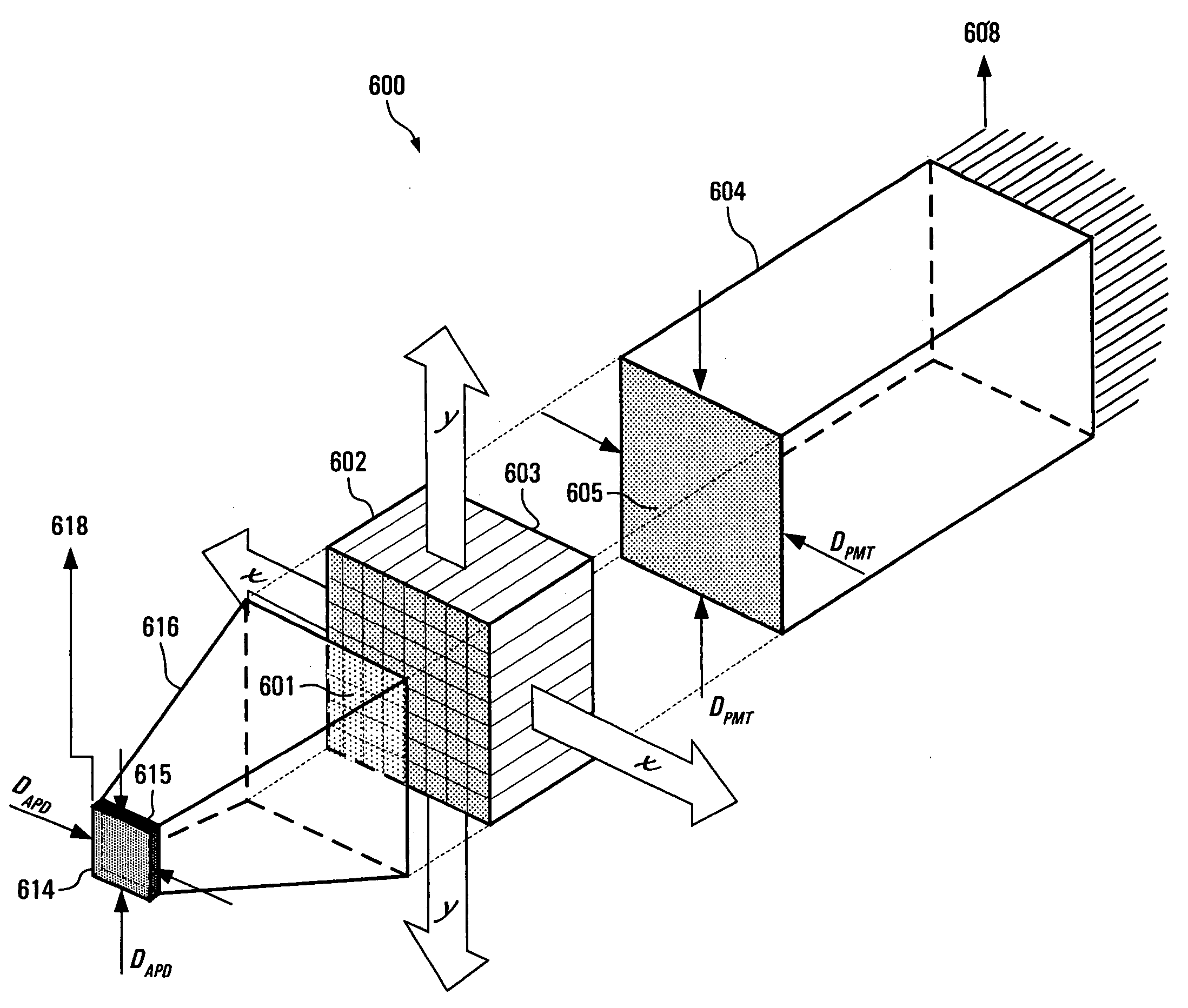
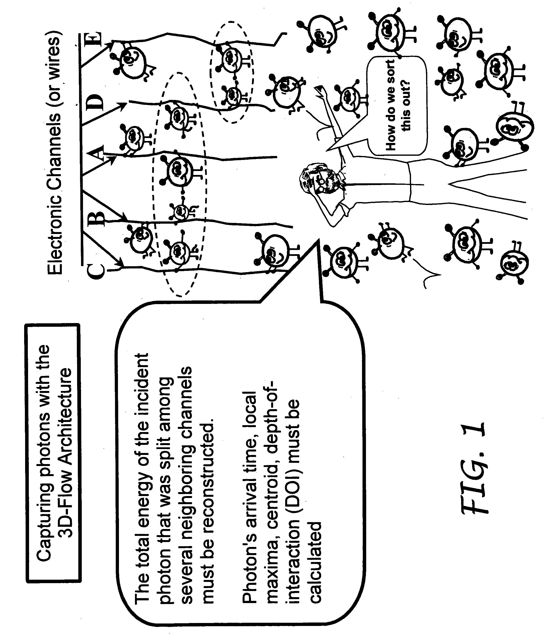
[0031] The present invention relates to improvements in processing data acquired from sensors coupled to detectors, enabling the alteration of altering detector placement, detector array spacing and detector field of view for increasing the capture rates of photons, and thereby increasing efficiencies of traditional Positron Emission Tomography (PET) devices on a photons per unit of radiation basis. It is a method and apparatus consisting of: [0032] a) A detector of photons covering a large surface of a human body (field of view-FOV); [0033] b) A particular detector assembly that best couples and transfers to the transducer and electronics the information generated by the interaction of a photon with the detector. [0034] c) An electronics with the capability to process most information arriving from the detector without the limitation of saturation or processing dead-time for any given radiation to the patient.

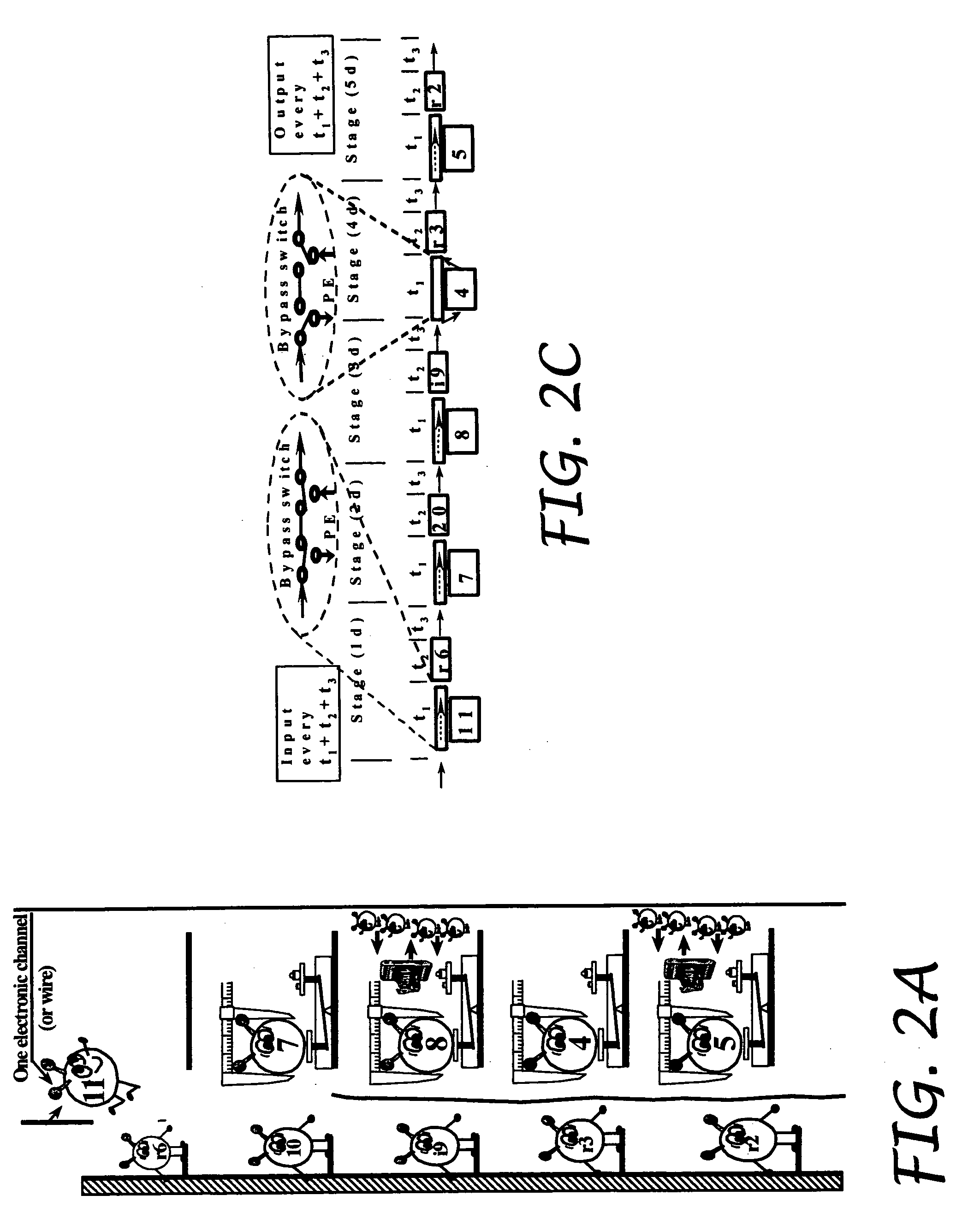
[0035] The electronics can acquire data faster than the decay time of an...


PUM


Abstract

The present invention is directed to a system and method for efficiently and cost effectively determining an accurate depth of interaction for a crystal that may be used for correcting parallax error and repositioning LORs for more clear and accurate imaging. The present invention is directed to a detector assembly having a thin sensor (e.g., APD) deployed in front of the detector (the side where the radioactive source is located and the photon is arriving to hit the detector) and a second sensor (APD or photomultiplier) on the opposite side of the detector. The light captured by the two interior and exterior sensors which is proportional to the energy of the incident photon and to the distance where the photon was absorbed by the detector with respect to the location of the two sensors, is converted into an electrical signal and interpolated for finding the distance from the two sensors which is proportional to the location where the photon hit the detector.

Description

CROSS REFERENCES TO RELATED APPLICATIONS [0001] The present application is a divisional of, and claims the benefit of priority from co-pending U.S. Non-Provisional patent application entitled, “Method and Apparatus for Three-Dimensional Complete Body Screening,” having application Ser. No. 10 / 376,024, and filed on Feb. 26, 2003, for inventions not disclosed in U.S. Provisional No. 60 / 360,301. Therefore, the present patent application does not seek benefit from U.S. Provisional No. 60 / 360,301 for the subject matters not disclosed therein. The present application is also related to, and claims the benefit of priority from co-pending U.S. Non-Provisional patent application entitled, “Method And Apparatus for Improving Pet Detectors,” having application Ser. No. ______, and filed on Nov. 11, 2003, attorney docket no. 510974-600005, which claims priority to U.S. Provisional Patent Application No. 60 / 424,933, of the same title and filed on Nov. 09, 2002 and each of which is incorporated b...

Claims


Application Information

Patent Timeline
Patent Type & Authority Applications(United States)
IPC IPC(8): G01T1/164G01T1/20
CPCG01T1/1642A61B6/037G01T1/2018G01T1/1644G01T1/20185
Inventor CROSETTO, DARIO B.
Owner CROSETTO DARIO B
Why Eureka
Try Eureka