Transmitting apparatus, sound sensor and autonomous traveling vehicle

a technology of transmitting apparatus and sound sensor, which is applied in the direction of mechanical vibration separation, instruments, and using reradiation, can solve problems such as unsolved conventional sound sensor problems, and achieve the effect of considerably reducing measurement error

Inactive Publication Date: 2005-10-20
SANYO ELECTRIC CO LTD
View PDF1 Cites 4 Cited by
  • Summary
  • Abstract
  • Description
  • Claims
  • Application Information

AI Technical Summary

Benefits of technology

[0012] The present inventors conducted researches including experiments with serious efforts for the purpose of decreasing a measurement error revealed as a time T2 shown in FIG. 1C mentioned above. Through the research, the present inventors have found that a response time of a vibration system including a piezoelectric element is reduced in a case where a frequency which drives the piezoelectric element is set to a fr

Problems solved by technology

The conventional sound sensor has had an unsolved problem that a measurement error, to be concrete, the time

Method used


Image

  • Transmitting apparatus, sound sensor and autonomous traveling vehicle
  • Transmitting apparatus, sound sensor and autonomous traveling vehicle
  • Transmitting apparatus, sound sensor and autonomous traveling vehicle

Examples


first embodiment

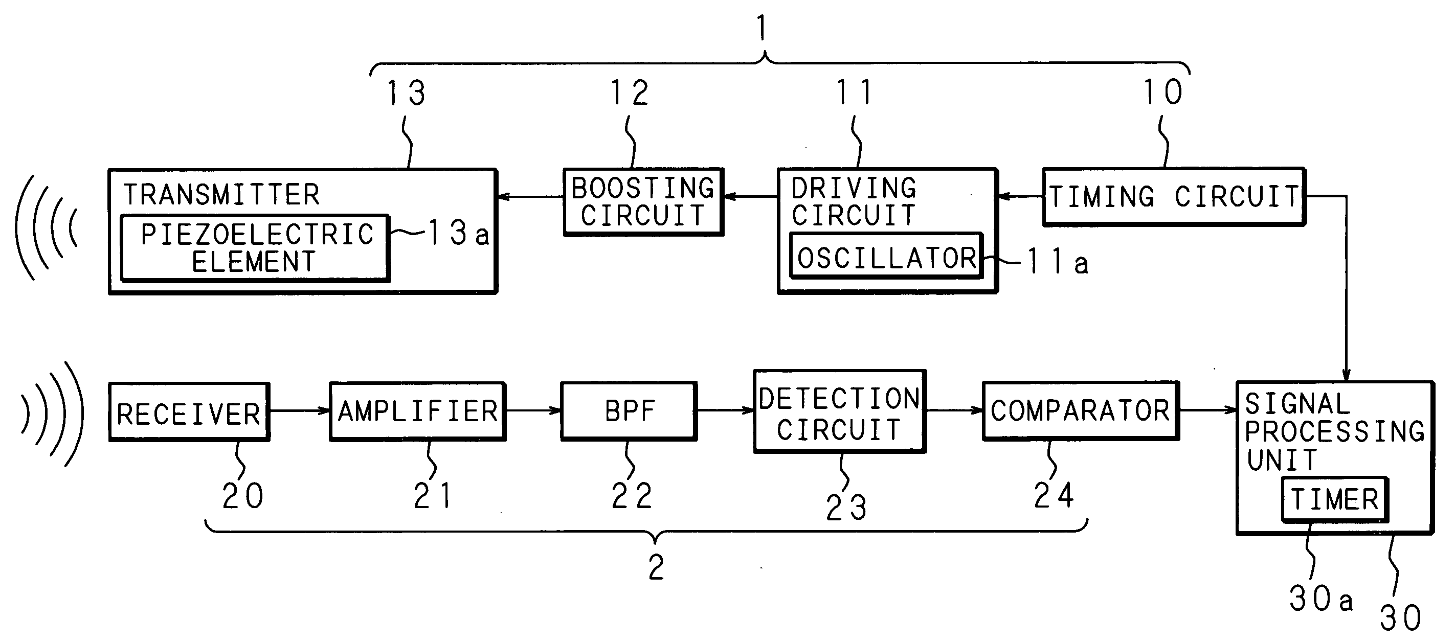
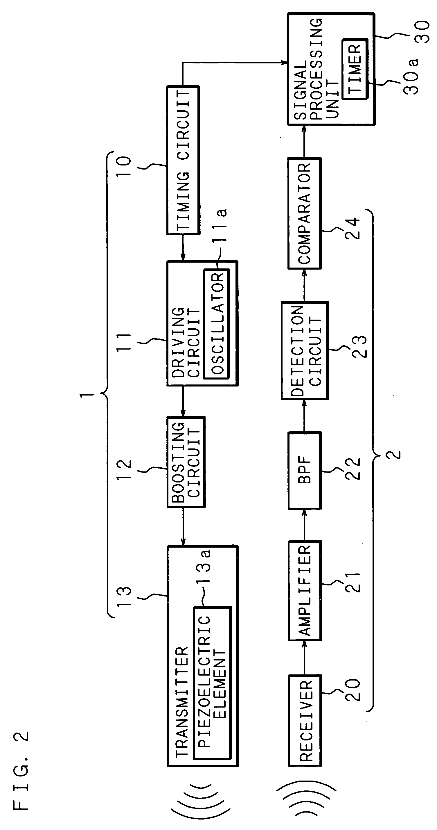
[0036] Detailed description will be given of the invention below on the basis of the accompanying drawings showing preferred embodiments thereof. FIG. 2 is a block diagram showing a schematic configuration of an ultrasonic sensor according to the invention.

[0037] An ultrasonic sensor according to the invention, as shown in FIG. 2, is, roughly speaking, constituted of a transmitting apparatus 1 according to the invention and a receiving apparatus 2 and further includes a signal processing unit 30. Such a ultrasonic sensor according to the invention is basically configured so that an acoustic wave is transmitted from the transmitting apparatus 1, the acoustic wave reflected by a detection-target object is received by the receiving apparatus 2, whereby a distance therefrom to the detection-target object is detected on the basis of an elapsed time until a reception time point from a transmission time point of the acoustic wave.

[0038] The transmitting apparatus 1 comprises a timing circ...

second embodiment

[0052]FIG. 5 is a block diagram showing a schematic configuration of a ultrasonic sensor according to the invention.

[0053] In FIG. 5, numeral 40 denotes a transmitter / receiver, which is equipped with a piezoelectric element 40a. The piezoelectric element 40a is applied with a voltage outputted from a boosting circuit 12 according to an oscillation signal of a frequency “f” outputted from an oscillator 11a of a driving circuit 11. The piezoelectric element 40a vibrates according to the frequency “f” of the applied voltage given from the boosting circuit 12 and transmits an acoustic wave.

[0054] The transmitter / receiver 40 receives an acoustic wave reflected by a detection-target object to generate an electric signal according to the vibration of the piezoelectric element 40a by the action of the received acoustic wave. The generated electric signal is inputted to the detection circuit 23 through an amplifier 21 and a BPF 22 in a similar way to that in the case of the above mentioned ...


PUM


Abstract

A driving circuit of a transmitting apparatus drives a piezoelectric element in a frequency band different from a resonance frequency at which a vibration system including the piezoelectric element resonates the most strongly. A driving circuit of a sound sensor drives the piezoelectric element for transmitting or receiving an acoustic wave in a frequency band different from a resonance frequency at which a vibration system including the piezoelectric element resonates the most strongly. Such a transmitting apparatus is mounted as a transmitting apparatus of a sound sensor to thereby realize the sound sensor with a small measurement error. The sound sensor is adopted for traveling control and steering control of an autonomous traveling vehicle to thereby enable an autonomous traveling vehicle capable of stopping in the vicinity of an obstacle to be realized.

Description

CROSS-REFERENCE TO RELATED APPLICATION [0001] This non-provisional application claims priority under 35 U.S.C. §119(a) on Patent Application No. 2004-104391 filed in Japan on Mar. 31, 2004, the entire contents of which are hereby incorporated by reference. BACKGROUND OF THE INVENTION [0002] 1. Field of the Invention [0003] The invention relates to a transmitting apparatus and a sound sensor for obtaining information such as the presence / absence of a detection-target object with an acoustic wave, or a distance therefrom to the detection-target object, and further relates to an autonomous traveling vehicle equipped with such a sound sensor. [0004] 2. Description of Related Art [0005] Conventionally, there has been known an ultrasonic sensor that transmits an ultrasonic wave to a detection-target object and, also, receives a reflected wave from the detection-target object to thereby measure a distance therefrom to the detection-target object on the basis of an elapsed time from a trans...

Claims


Application Information

Patent Timeline
IPC IPC(8): B06B1/02H04R1/20B06B1/06G01S7/524G01S15/58G01S15/931G05D1/02G10K9/122H01L41/00H01L41/08H04R17/00
CPCB06B1/0238G05D2201/0203G05D1/0255G01S15/931G05D3/00
Inventor TOKUMARU, TOMOYOSHIHIROSE, TATSUYA
Owner SANYO ELECTRIC CO LTD
Why Eureka
Try Eureka