Method and apparatus for continuous readout of Fabry-Perot fiber optic sensor

a fiber optic sensor and fiber optic sensor technology, applied in the field of fabryperot fiber optic sensor and tunable laser combination system, can solve the problems of inability to precisely measure and control the laser wavelength, limited the range of gaps measurable by prior art laser-based fabryperot sensors, etc., and achieve the effect of improving the performance of the system

Active Publication Date: 2005-10-20
HALLIBURTON ENERGY SERVICES INC
View PDF99 Cites 38 Cited by
  • Summary
  • Abstract
  • Description
  • Claims
  • Application Information

AI Technical Summary

Benefits of technology

[0006] A method for monitoring and quantitatively measuring small displacements in a Fabry-Perot sensor is also contemplated. The method includes interrogating the reflective surfaces bounding a variable unknown gap in the Fabry-Perot sensor using a frequency-tunable laser light. The laser light is provided over a range of frequencies, and the intensity of the laser light modulated by the Fabry-Perot sensor is monitored to identify at least two minima. An absolute value of the distance of the unknown gap can then be calculated from these minima. In turn, the absolute value for the unknown variable gap may be used to calculate and monitor an environmental parameter of the Fabry-Perot sensor—most likely the pressure applied to one of the reflective surfaces in the sensors. Optional temperature correction and / or laser pulsing can be performed to enhance the performance of the system. Additional interrogation of the sensor over a reduced range of laser frequencies for fast scan monitoring of the variable gap is also contemplated.

Problems solved by technology

Consequently, the teachings of the McClintock patent do not apply to Fabry-Perot sensors in the art, especially with respect to the methodology used to perform the calculation of gap length.
Notably, both with respect to the McClintock patent and the other prior references known to the inventors, the range of gaps measurable by prior art laser-based Fabry-Perot sensors were limited in practice by the wavelength and tuning range of the laser.
Other errors in such systems resulted from laser instabilities and inability to precisely measure and control laser wavelength.

Method used


Image

  • Method and apparatus for continuous readout of Fabry-Perot fiber optic sensor
  • Method and apparatus for continuous readout of Fabry-Perot fiber optic sensor
  • Method and apparatus for continuous readout of Fabry-Perot fiber optic sensor

Examples


Embodiment Construction

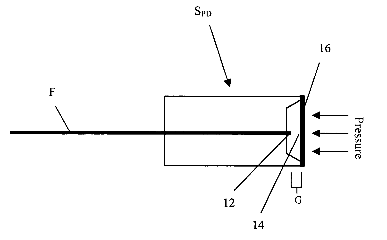
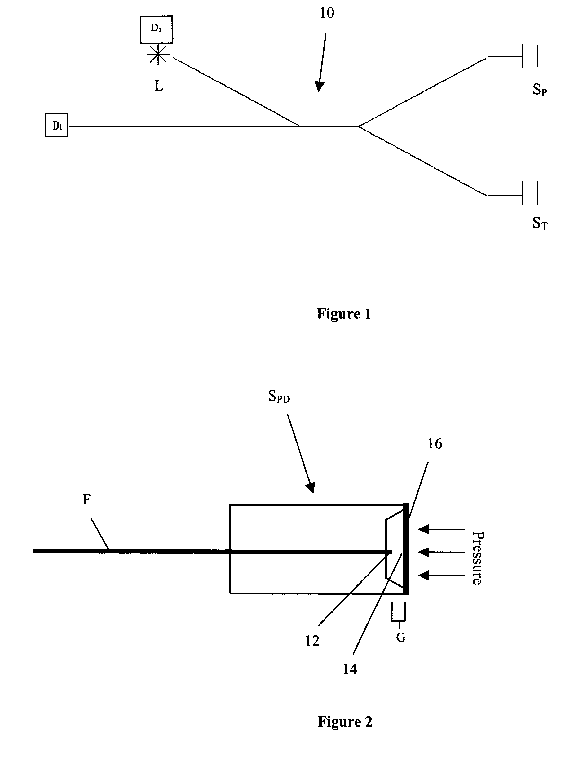
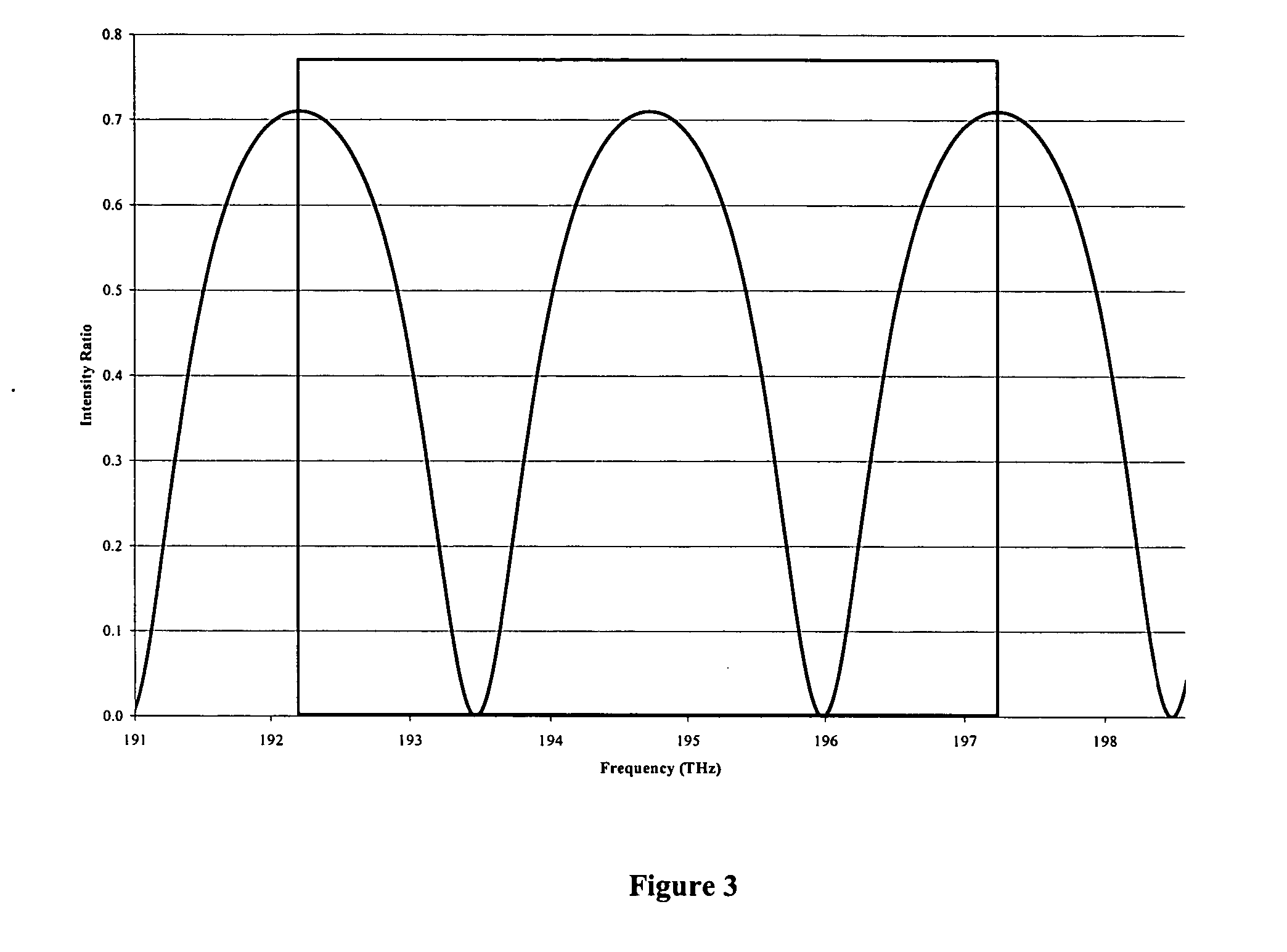
[0013] This invention is a new approach for using fiber optic Fabry-Perot sensors to make high-resolution temperature and pressure measurements at long distances between the sensor and the signal conditioning system. The approach requires a high power, tunable laser that can provide rapid switching in fine increments in narrow wavelength bands with repeatability in the infrared spectral band from 1500 to 1600 nm. Such tunable lasers with very wide tuning range have recently become commercially available. By operating in the 1500 to 1600 nm spectral band where attenuation in optical fiber is very low, high resolution pressure and temperature measurements can be made using Fabry-Perot sensors at remote distances in excess of 10000 meters with update rates of 10 Hz.

[0014] A schematic of the invention 10 is shown in FIG. 1. Infrared light from the laser L is injected into a multimode optical fiber (50 μm / 125 μm for example), where it passes through a power splitter and thence to two se...


PUM

PropertyMeasurementUnit
reflectivityaaaaaaaaaa
wavelengthaaaaaaaaaa
gap distanceaaaaaaaaaa

Abstract

A pressure measurement system and method are described. The system uses a tunable laser and a Fabry-Perot sensor with integrated transducer. A detector senses the light modulated by the Fabry-Perot sensor. A signal conditioner, which can be located up to 15 km away, then uses the detector signal to determine the displacement of the diaphragm, which is indicative of pressure exerted against the diaphragm. Use of a temperature sensor to generate a signal, fed to the signal conditioner, to compensate for temperature is also contemplated.

Description

FIELD AND BACKGROUND OF INVENTION [0001] The present invention relates to a Fabry-Perot fiber optic sensor and, more particularly, to a high finesse Fabry-Perot sensor and tunable laser combination system for measuring small displacements. This application claims the benefit of U.S. Ser. No. 60 / 562,430, filed Apr. 15, 2004. [0002] Low finesse Fabry-Perot interferometers have a reflectivity of approx. 50% or less. Such interferometers have been used in sensors in order to provide an indication as to the displacement of a gap between two reflective surfaces. For example, U.S. Pat. No. 5,276,501 to McClintock et al. describes a low-finesse Fabry-Perot fiber optic sensor that uses a laser of limited tuning range. The laser itself is tuned via temperature control to operate at two different wavelengths. Notably, reflectivity of the sensor is in the range of 4%, and the readout from the sensor is approximated as a two beam interferometer so that the gap length is a function of wavelength ...

Claims


Application Information

Patent Timeline
Patent Type & Authority Applications(United States)
IPC IPC(8): G01B9/02G01D5/26G01D5/353G01L9/00
CPCG01D5/268G01D5/35303G01B2290/25G01B9/02004G01B9/02023G01L9/0079
Inventor LOPUSHANSKY, RICHARD L.BERTHOLD, JOHN W.
Owner HALLIBURTON ENERGY SERVICES INC
Why Eureka
Try Eureka