Substrate treating method and apparatus

a technology for treating methods and substrates, applied in the direction of cleaning processes and equipment, chemistry apparatus and processes, cleaning using liquids, etc., can solve the problems of prolonging the time consumed in cleaning substrates with deionized water, consuming a large amount of deionized water, and requiring a long time to replace chemical solutions, etc., to improve deionized water cleaning treatment, reduce the number of treating steps, and reduce the consumption of deionized water

Inactive Publication Date: 2005-10-27
DAINIPPON SCREEN MTG CO LTD
View PDF1 Cites 24 Cited by
  • Summary
  • Abstract
  • Description
  • Claims
  • Application Information

AI Technical Summary

Benefits of technology

[0007] This invention has been made having regard to the state of the art noted above, and its object is to provide a substrate treating method and apparatus for performing i

Problems solved by technology

It has been found that the deionized water cleaning treatment performed after chemical treatment requires a long time because water flows are hampered by boundary films formed adjacent the substrate surfaces.
That is, the boundary films worsen the

Method used


Image

  • Substrate treating method and apparatus
  • Substrate treating method and apparatus
  • Substrate treating method and apparatus

Examples


embodiment 1

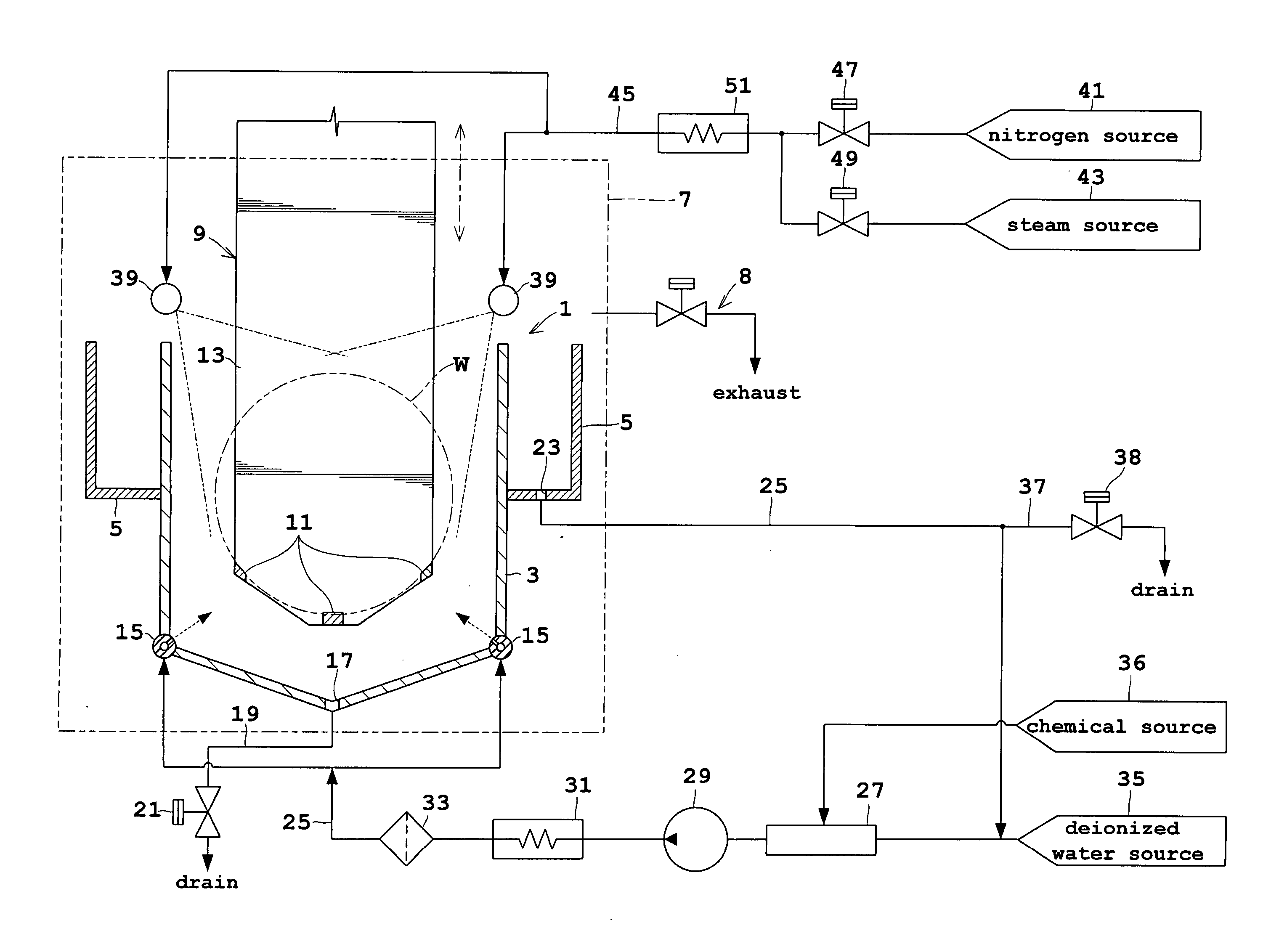
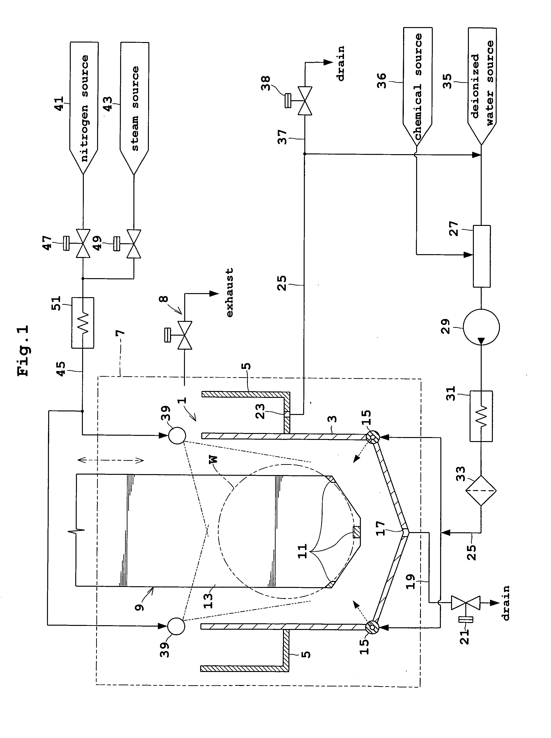
[0039]FIG. 1 is a block diagram showing an outline of a substrate treating apparatus according to Embodiment 1.

[0040] A treating tank 1 for treating wafers W includes an inner tank 3 and an outer tank 5. The treating tank 1 as a whole is enclosed in a chamber 7. The chamber 7 has a transport opening, not shown, in an upper position thereof for allowing passage of the wafers W into and out of the chamber 7, and an exhaust mechanism 8 with piping and a switch valve for discharging internal gas. The inner tank 3 accommodates a plurality of wafers W as held by a lifter 9, and treats the wafers W with a chemical solution and so on. The lifter 9 includes a three-piece support member 11 extending from lower positions of a back plate 13 for contacting and supporting lower edges of wafers W. The lifter 9 depicted in FIG. 1 is in a treating position inside the inner tank 3, and is vertically movable between this treating position and a standby position above the chamber 7.

[0041] The inner t...

embodiment 2

[0051] Next, Embodiment 2 of this invention will be described with reference to the drawings.

[0052]FIG. 6 is a block diagram showing an outline of a substrate treating apparatus according to Embodiment 2.

[0053] The substrate treating apparatus in Embodiment 1 described above is what is called the “batch type” that treats a plurality of wafers W at once. The substrate treating apparatus in this embodiment is different, and is what is called the “single-substrate type” that treats one wafer W at a time.

[0054] This apparatus includes a holding mechanism 61 for supporting a wafer W in horizontal posture, and a chamber 63 surrounding the holding mechanism 61. The holding mechanism 61 includes a member having an outside diameter slightly larger than the outside diameter of wafer W. This member has through holes 65 formed in positions corresponding to vertices of its equilateral triangular shape in plan view. The holding mechanism 61 further includes a heater 67 mounted therein for heat...


PUM


Abstract

A substrate treating method for performing a predetermined treatment of substrates. The method includes a step of performing chemical treatment of the substrates with a chemical, and a step of performing deionized water cleaning treatment of the substrates with superheated steam obtained by heating deionized water.

Description

BACKGROUND OF THE INVENTION [0001] (1) Field of the Invention [0002] This invention relates to substrate treating methods and apparatus for treating semiconductor wafers, glass substrates for liquid crystal displays and so on (hereinafter called simply substrates). More particularly, the invention relates to a technique for performing treatment of substrates, including chemical treatment and deionized water (pure water) cleaning treatment. [0003] (2) Description of the Related Art [0004] Conventionally, this type of substrate treating apparatus performs chemical treatment by loading substrates into a treating tank and supplying a chemical solution to the tank. After discharging the chemical solution, deionized water is supplied to the treating tank, and the apparatus performs deionized water cleaning treatment of the substrates immersed in the deionized water, while allowing the deionized water to overflow the tank (see Japanese Unexamined Patent Publication No. 11-162921 (1999), fo...

Claims


Application Information

Patent Timeline
IPC IPC(8): H01L21/304B08B3/00B08B3/02H01L21/00H01L21/02
CPCB08B3/02B08B2230/01H01L21/67051H01L21/67028H01L21/02052
Inventor NAGAMI, SHUZO
Owner DAINIPPON SCREEN MTG CO LTD
Why Eureka
Try Eureka