Compliant hard template for UV imprinting

Active Publication Date: 2005-10-27
CANON KK
View PDF99 Cites 22 Cited by
  • Summary
  • Abstract
  • Description
  • Claims
  • Application Information

AI Technical Summary

Benefits of technology

[0010] In an embodiment of the present invention, the template comprises an imprinting layer, where the imprinting layer includes first and second parallel surfaces and the first surface includes an imprinting area having a relief image; an elastomer; and a substrate, where the elastomer is arranged between the substrate and the second surface of the imprinting layer. In an embodiment, the elastomer is less rigid than the substrate. In an embodiment, the elastomer is le

Problems solved by technology

However, optical systems are limited in their ability to resolve very small features.
Further, increasing numerical aperture results in a significant depth of focus loss, as shown in the following equation, where again λ is wavelength and NA is numerical aperture:
Accordingly, optical lithography systems capable of printing microstructures may require a depth of focus so small as to be intolerant of slight wafer non-planarity, which commonly

Method used


Image

  • Compliant hard template for UV imprinting
  • Compliant hard template for UV imprinting
  • Compliant hard template for UV imprinting

Examples


Embodiment Construction

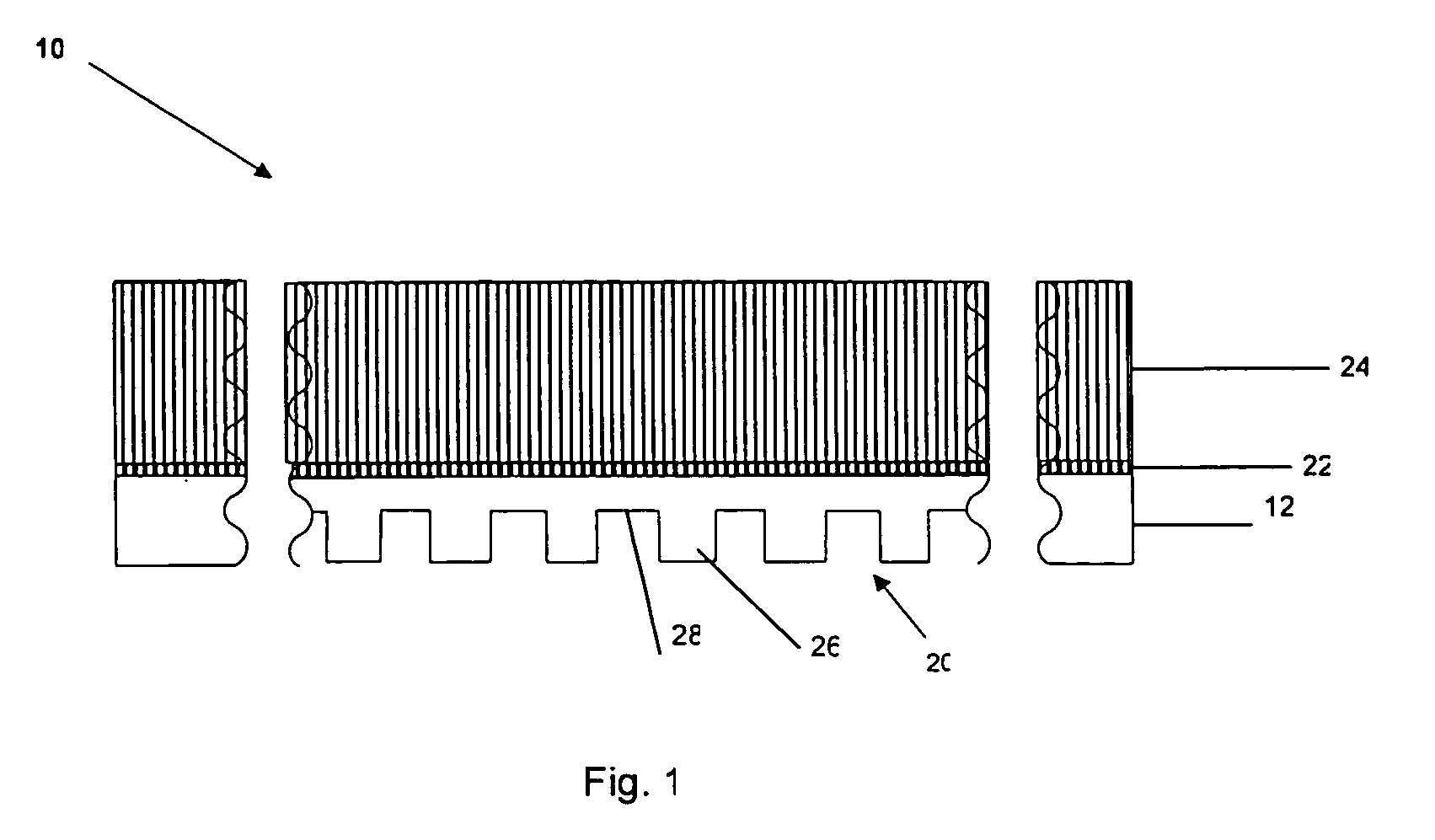
[0029] Referring to FIG. 1, a template 10 in accordance with an embodiment of the present invention includes an imprinting layer 12, having a relief image 20 therein, an elastomer layer 22 and a substrate 24. Elastomer layer 22 is disposed between imprinting layer 12 and substrate 24. Template 10 is designed for use an imprint lithography system wherein template 10 is urged into a formable material to imprint the same with a pattern that corresponds to relief image 20 for patterned material. The patterned material is subsequently solidified upon exposure to actinic radiation, e.g. ultraviolet radiation, thermal radiation and the like. An exemplary lithographic system is available under the trade name IMPRIO 100™ from Molecular Imprints, Inc., having a place of business at 1807-C Braker Lane, Suite 100, Austin, Tex. 78758. The system description for the IMPRIO 100™ is available at www.molecularimprints.com and is incorporated herein by reference. As a result, substrate 24, elastomer ...


PUM

PropertyMeasurementUnit
Nanoscale particle sizeaaaaaaaaaa
Electrical conductoraaaaaaaaaa
Areaaaaaaaaaaa

Abstract

A compliant UV imprint lithography template, which may also act as a thermal implant template, and methods for manufacturing it. The template essentially comprises a relief image and an elastomer adapted to adjust the relief image. In an embodiment, the relief image is arranged in a compliant imprinting layer where the elastomer is arranged between the imprinting layer and a rigid transparent substrate. In an embodiment, the template is compliant to a wafer surface. In an embodiment, layering an elastomer and an imprinting layer on a substrate and patterning a relief image into the imprinting layer, form the template.

Description

BACKGROUND OF THE INVENTION [0001] 1. Field of the Invention [0002] The present invention relates to imprint lithography templates suitable for use in micro-fabrication of structures. The compliant template herein described has particular utility in pattern transfer onto non-planar surfaces. [0003] 2. Description of the Related Art [0004] Micro-fabrication involves the fabrication of very small structures, e.g., having features on the order of micrometers or smaller. One industry that has been driving the fabrication of increasingly smaller structures is the electronics industry. As electronic devices have become smaller and faster, the integrated circuits that drive them have necessarily become smaller. [0005] Lithographic techniques are usually employed in the manufacture of integrated circuits. Typically, these lithographic techniques include applying photosensitive materials to a semiconductor substrate. These photosensitive materials, commonly referred to as “resist,” are selec...

Claims


Application Information

Patent Timeline
IPC IPC(8): B44C1/22
CPCB29C43/003B29C2043/025G03F7/0017B82Y40/00G03F7/0002B82Y10/00B44C1/22
Inventor WATTS, MICHAEL P.C.VOISIN, RONALD D.SREENIVASAN, SIDLGATA V.
Owner CANON KK
Why Eureka
Try Eureka