

Ultrashort pulse laser processing method
a laser processing method and ultrashort pulse technology, applied in the direction of manufacturing tools, metal working equipment, welding/soldering/cutting articles, etc., can solve problems such as tunneling and potential strain
- Summary
- Abstract
- Description
- Claims
- Application Information
AI Technical Summary
Problems solved by technology
Method used
Image

Examples
first embodiment
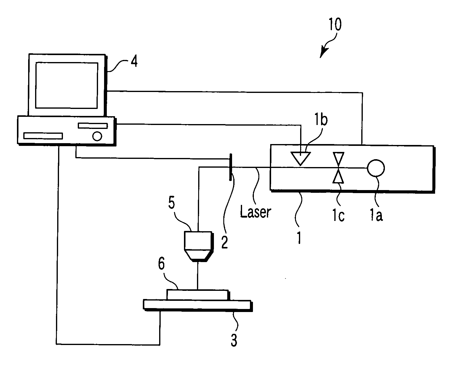
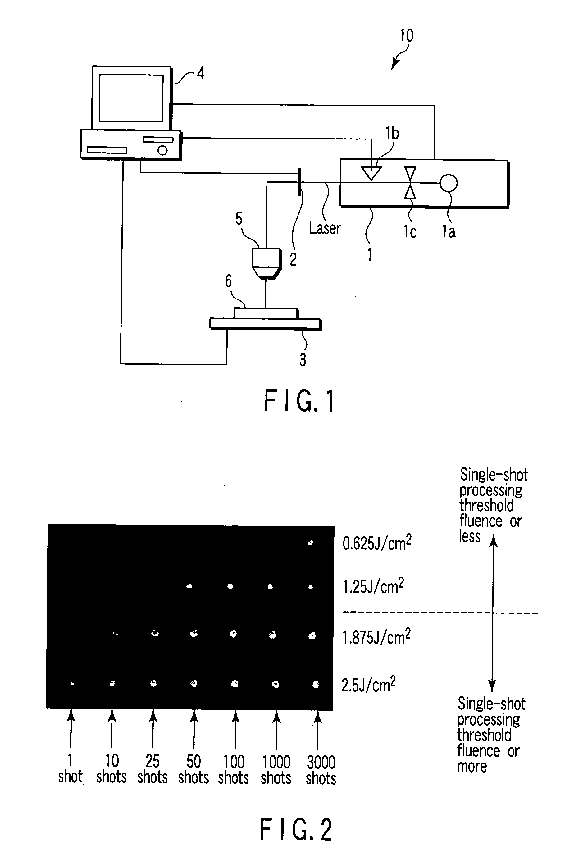
[0021]FIG. 1 is a diagram showing an entire configuration of an ultrashort pulse laser processing device 10 for realizing an ultrashort pulse laser processing method of the present invention. The ultrashort pulse laser processing device 10 comprises an ultrashort pulse laser generator 1, a shutter 2, a stage 3, a computer 4 and a converging optical system 5. An article 6 which is a processing target is mounted on the stage 3 and processed.
[0022] A laser beam generated from the ultrashort pulse laser generator 1 enters the converging optical system 5 through the shutter 2. The converging optical system 5 forms the laser beam into a desired beam shape, and converges the laser beam on a surface of the article to be processed 6 or on a predetermined position therein. As the converging optical system 5, for example, a single aspherical lens is used. For example, the article to be processed 6 is a metal, a wafer, a glass, a crystal material, a biomaterial, or a resin. According to the em...
second embodiment
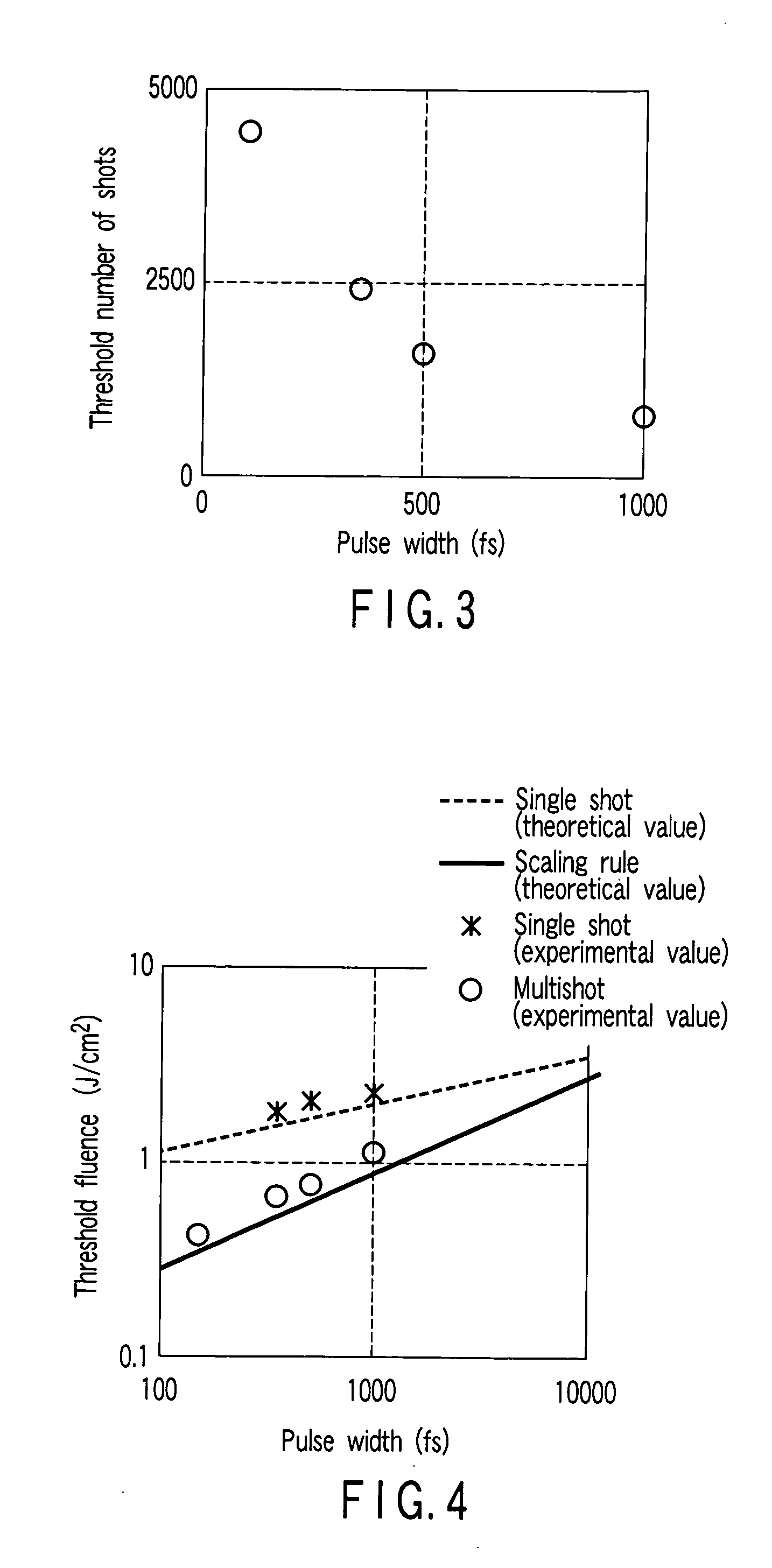
[0039] The embodiment is a modified example of the first embodiment. The embodiment is characterized in that a pulse width and the threshold number of shots are calculated by analysis based on a multiphoton absorption process and laser processing is carried out based on the obtained threshold number of shots. A device configuration for realizing the embodiment is similar to that of the first embodiment shown in FIG. 1.
[0040] First, in abrasion processing of a BK 7, by using a computer 4 or another computer, processing in an ultrashort pulse area compliant with a scaling rule is assumed to be a 2-photon absorption process, and a relationship between a pulse width and the threshold number of the shots is calculated by analysis. FIG. 3 shows the calculated relationship between the pulse width and the threshold number of the shots.
[0041] Then, the obtained threshold number of shots is set as the number of shots, and laser irradiation is performed at various fluences by using an ultras...
third embodiment
[0046] The embodiment is a modified example of the first embodiment. While the first embodiment shows the example of executing abrasion as laser processing, this embodiment is characterized by setting a laser focus in an article to 6 to be processed and modifying the inside thereof. A device configuration for realizing the embodiment is similar to that of the first embodiment shown in FIG. 1.
[0047] According to the embodiment, a BK 7 is used as the article to be processed 6. Arrangements other than setting of a converging point of a converging optical system 5 in a glass of the article to be processed 6 are similar to those of the first embodiment. That is, a laser pulse from an ultrashort pulse laser generator 1 is converged in the article to be processed 6 by using the converging optical system 5. Accordingly, the inside of the article to be processed 6 is modified. A refraction index is changed in the modified area. By observing the change in refractive index, presence of laser ...
PUM
| Property | Measurement | Unit |
|---|---|---|
| frequency | aaaaa | aaaaa |
| frequency | aaaaa | aaaaa |
| frequency | aaaaa | aaaaa |
Abstract
Description
Claims
Application Information