Plasma display device and method for driving the same

a plasma display device and drive method technology, applied in the field of alternating current (ac) discharge plasma display devices and drive methods there, can solve the problems of excessive priming discharge, increased discharge start voltage, excessive priming discharge, etc., and achieves excellent and stable display quality, decrease potential difference, and increase potential difference

Inactive Publication Date: 2005-10-27
PANASONIC CORP
View PDF5 Cites 27 Cited by
  • Summary
  • Abstract
  • Description
  • Claims
  • Application Information

AI Technical Summary

Benefits of technology

[0051] In still another alternative manner, the priming period may include a first period for successively increasing the potential difference between the scan electrodes and the sustain electrodes, and a second period for decreasing the potential difference. Based on the estimation result derived for the discharge start voltage, the start time is calculated for the priming discharge in the first period. When the calculated start time is a first time, the transition timing from the first period to the second period may be delayed compared with in a case where the start time is a second time that is earlier than the first time. In this manner, the priming discharge stops at the transition from the

Problems solved by technology

With such a conventional technology, however, there are the following problems.
This resultantly increases the discharge start voltage.
Therefore, when the PDP is high in temperature, the priming discharge does not continue that long compared with when the PDP is at the normal temperature, and thus the priming discharge is not enough.
Thus set priming voltage Vp is unnecessarily high for the normal conditions with the low discharge start voltage, resultantly causing the priming discharge to be excessive.
The resulting excessive priming discharge raises the black level, thereby lowering the image contrast.
Even if the priming discharge occurs, the resulting level is not enough.
This results in writing failure for some display cells with no writing discharge occurred.
In the display cells ob

Method used


Image

  • Plasma display device and method for driving the same
  • Plasma display device and method for driving the same
  • Plasma display device and method for driving the same

Examples


first embodiment

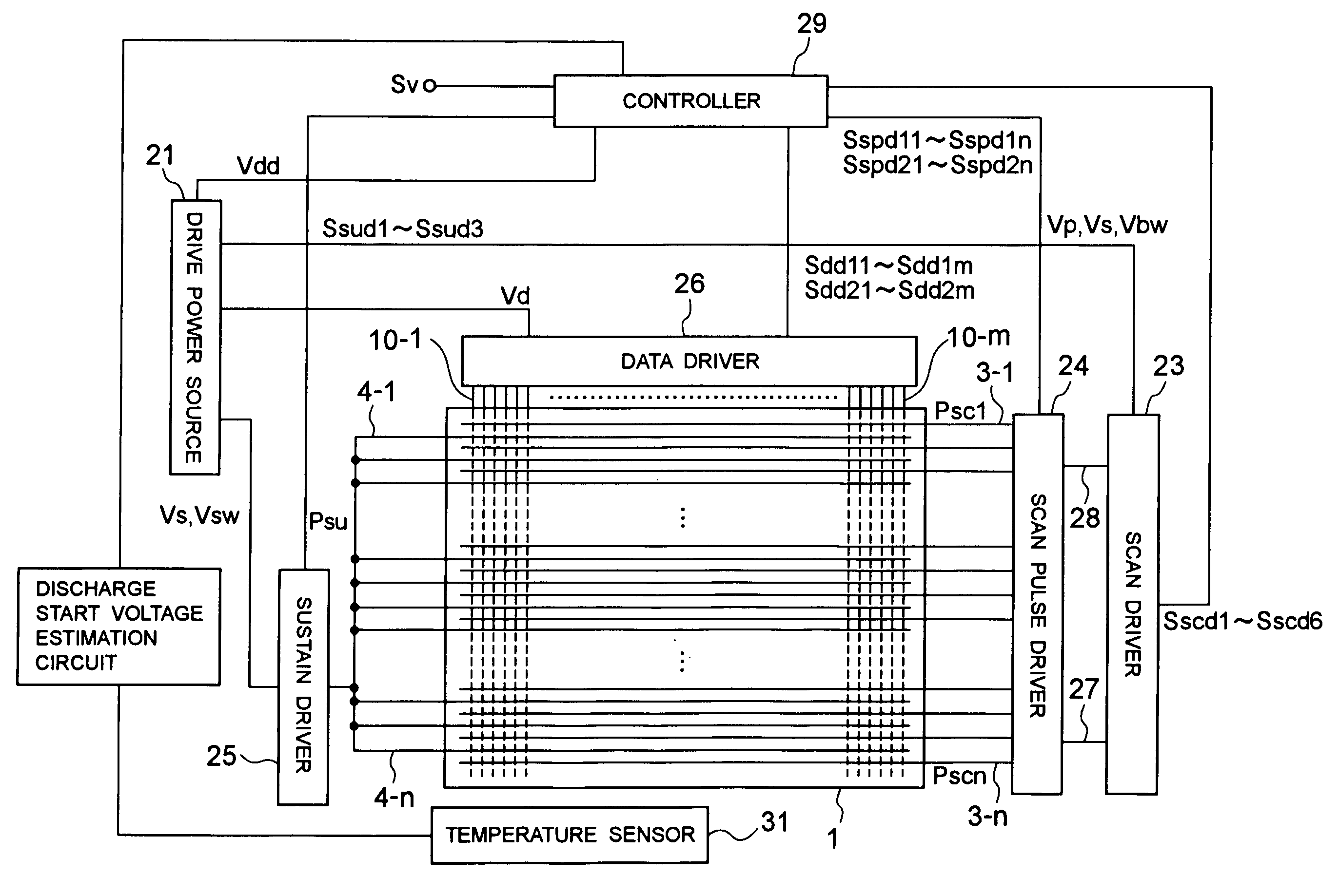
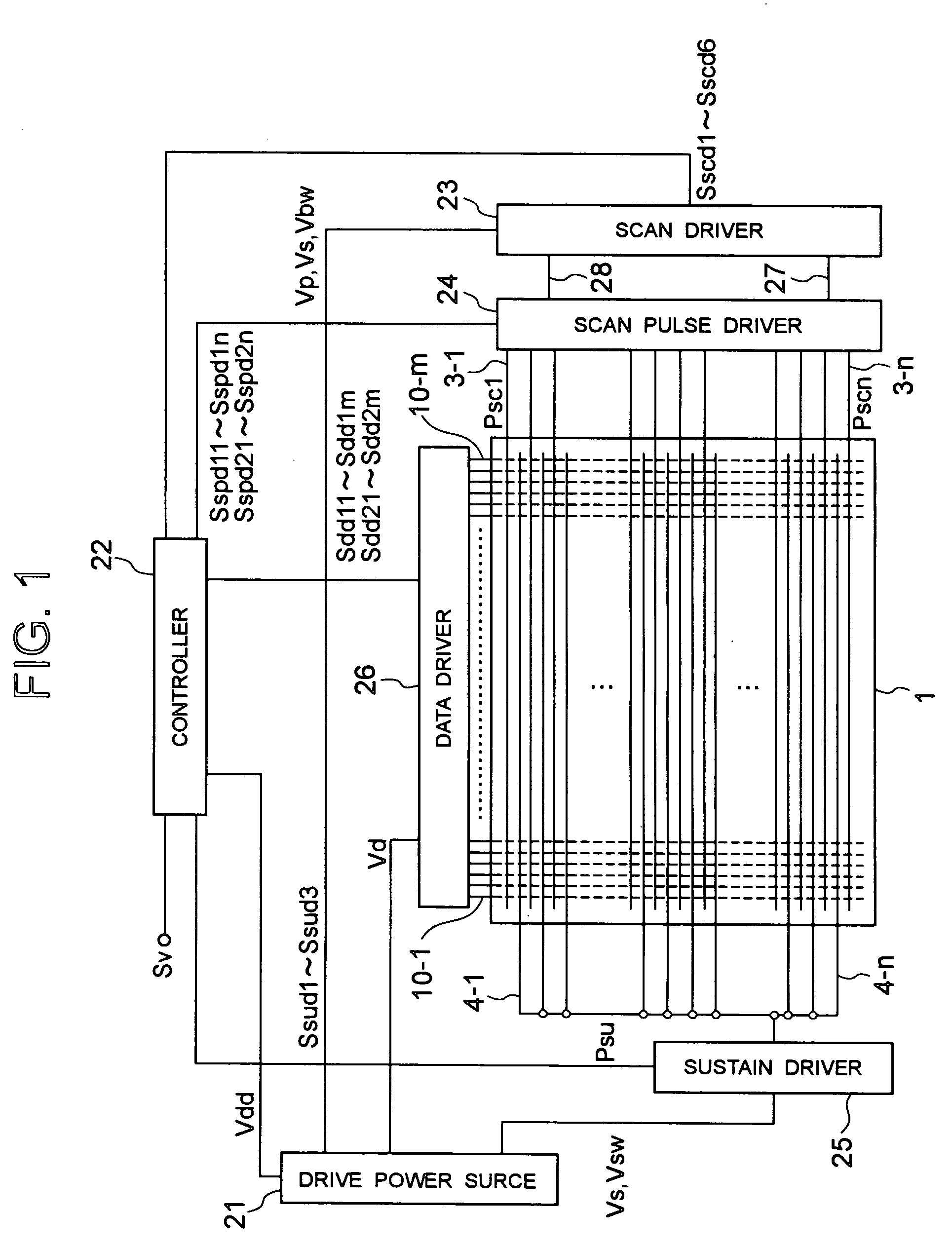
[0068] As shown in FIG. 8, the plasma display device of this first embodiment is provided with a temperature sensor 31 for measuring the temperature of the display panel 1. The temperature sensor 31 is singly or plurally provided at such positions that the insulation substrates 101 and 102 (refer to FIG. 5) of the display panel 1 can be measured for their temperature. The temperature sensor 31 is exemplarily a sensor provided with a thermocouple at the position where the heat comes from the display panel 1. For example, the temperature sensor 31 is singly attached to a digital package (not shown) that is placed at the back of the display panel 1.

[0069] In the plasma display device of this first embodiment, a discharge start voltage estimation circuit 32 is so provided as to receive output signals of the temperature sensor 31. The discharge start voltage estimation circuit 32 stores data indicating the correlation between the temperature of the display panel 1 and the discharge start...

second embodiment

[0079] Described next is the operation of the plasma display device of this second embodiment configured as above, i.e., the method for driving the plasma display device of this embodiment. FIG. 11 is a timing chart showing the priming operation of the plasma display device of this embodiment.

[0080] By referring back to FIG. 8, during when the plasma display device is in operation, the measurement sensor 31 measures the temperature of the display panel 1, and the measurement result is forwarded to the discharge start voltage estimation circuit 32. The discharge start voltage estimation circuit 32 estimates the discharge start voltage, and outputs the estimated value to the controller 29. Such voltage estimation is made based on the measurement result provided by the temperature sensor 31.

[0081] As shown in FIG. 11, based on the estimated value of the discharge start voltage, the controller 29 (refer to FIG. 8) controls the gate voltage of the field-effect transistor connected to th...

third embodiment

[0094] Described next is the operation of the plasma display device of this third embodiment configured as above, i.e., the method for driving the plasma display device of this embodiment. FIG. 14 is a timing chart showing the priming operation of the plasma display device of this embodiment.

[0095] Described first is the operation at start-up of the plasma display device, i.e., the operation in a period when the output signals coming from the timer 35 are high in level. As shown in FIG. 12, when the plasma display device having been in the stopped state is activated, the drive power source 33 is activated, and supplies the logic voltage Vdd to the timer 35. In response, the timer 35 starts time measurement, and outputs high-level signals to the controller 30. The controller 30 displays on the display panel 1 images based on the video signal Sv.

[0096] When the output signals coming from the timer 35 are high in level, as shown in FIG. 14, the controller 30 changes the level of contr...


PUM


Abstract

When a discharge start voltage takes a normal value under the normal temperature, priming discharge starts at a time t1. In this case, at a time t3 that is later than the time t1 by a predetermined time t, a sustain driver control signal Ssud2 is raised to put a sustain electrode into the floating state to stop the priming discharge. When the discharge start voltage takes a higher value than usual under the high temperature, the priming discharge starts at a time t2. In this case, at a time t4 that is later than the time t2 by the predetermined time t, the sustain driver control signal Ssud2 is lowered to put the sustain electrode into the floating state to stop the priming discharge. With such a configuration, provided is a plasma display device capable of implementing excellent and stable display quality while maintaining constant, even if a discharge start voltage varies, the charge state in display cells after a priming period, and a drive method for such a plasma display device.

Description

BACKGROUND OF THE INVENTION [0001] 1. Field of the Invention [0002] The present invention relates to alternating-current (AC) discharge plasma display devices and drive methods therefor. [0003] 2. Description of the Related Background Art [0004] Plasma display devices including plasma display panels (in the below, referred also to as PDPs) serving as display panels generally have many advantages, e.g., thin-and-large-screen display with relative ease, wider viewing angle, and faster response speed. With such various advantages, the PDPs have recently become popular for use as flat displays of wall televisions, public display boards, and others. The PDPs are classified into two types of direct-current (DC) discharge PDPs and AC discharge PDPs according to their operation mode. The DC-type PDPs operate in response to direct-current discharge between electrodes, which are exposed to the discharge space filled with discharge gas. The AC-type PDPs operate under the conditions of AC disch...

Claims


Application Information

Patent Timeline
IPC IPC(8): G09G3/28G09G3/288
CPCG09G2320/041G09G3/2927A61H7/003A61H9/0078A47K7/04A61H2201/1685A61H2201/1695A61H2201/0103A61H2205/021A61H2205/022
Inventor TSUCHIDA, SHINYAHIRAKAWA, SHINJIISHIZUKA, MITSUHIROHASHIMOTO, KOJIHOMMA, HAJIME
Owner PANASONIC CORP
Why Eureka
Try Eureka