Mirror unit, method of producing the same, and exposure apparatus and method using the mirror unit

a mirror unit and mirror technology, applied in the field of mirror systems, can solve the problems of surface shape deformation by its own self-, the effect of reducing the shape error of the reflection surface only by polishing into the allowable range such as described above,

Inactive Publication Date: 2005-10-27
CANON KK
View PDF3 Cites 13 Cited by
  • Summary
  • Abstract
  • Description
  • Claims
  • Application Information

AI Technical Summary

Benefits of technology

[0022] It is accordingly an object of the present invention to provide a multilayered film mirror or a mirror unit by which at least one of the inconveniences described above can be solved or reduced.

Problems solved by technology

However, form the standpoint of production, reducing the shape error of the reflection surface only by the polishing into the allowable range such as described above is practically very difficult.
Furthermore, there is a possibility that the surface shape deforms by its self-weight or when it is put on a mounting member or the like.

Method used


Image

  • Mirror unit, method of producing the same, and exposure apparatus and method using the mirror unit
  • Mirror unit, method of producing the same, and exposure apparatus and method using the mirror unit
  • Mirror unit, method of producing the same, and exposure apparatus and method using the mirror unit

Examples


embodiment 1

[Embodiment 1]

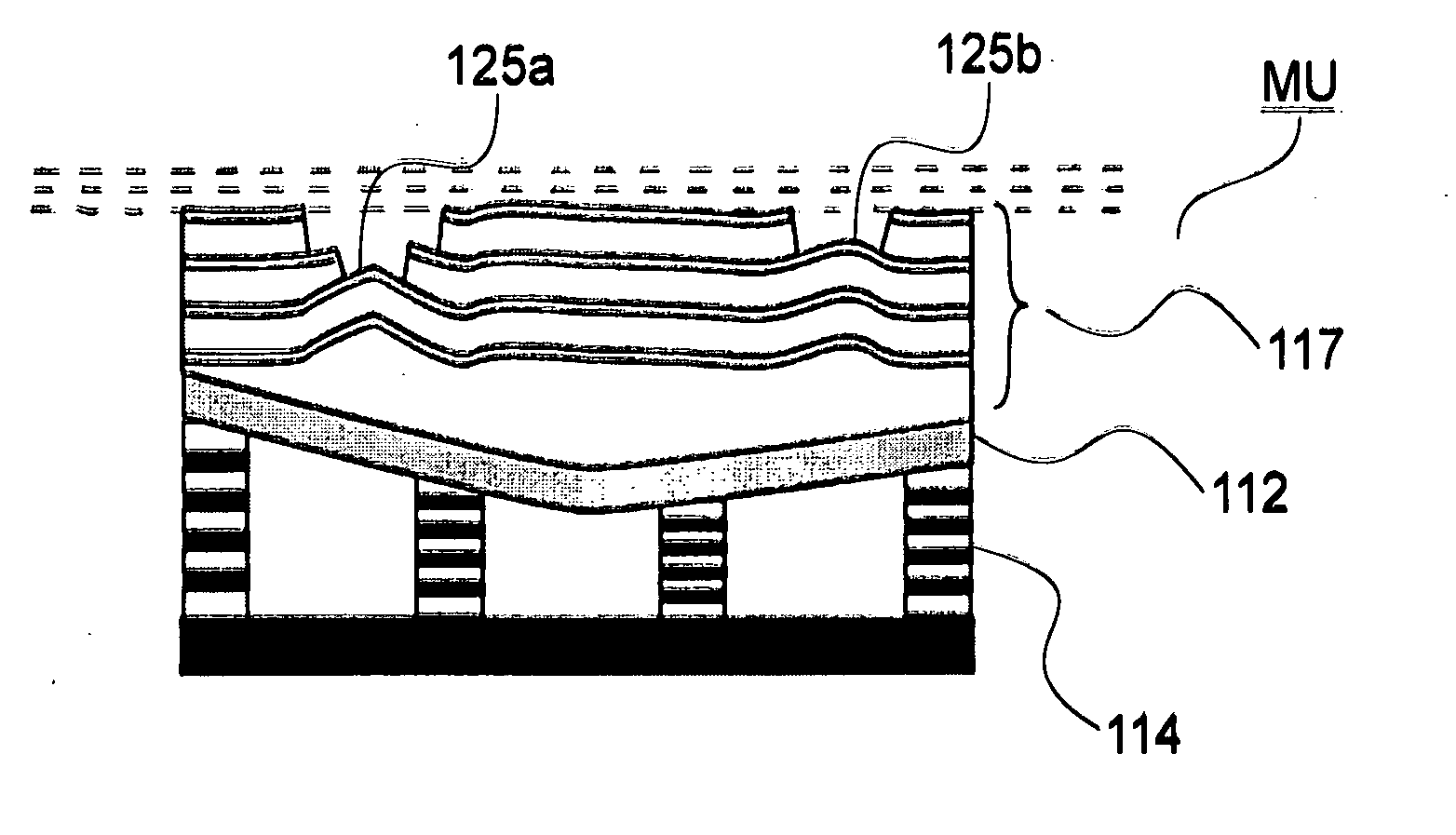
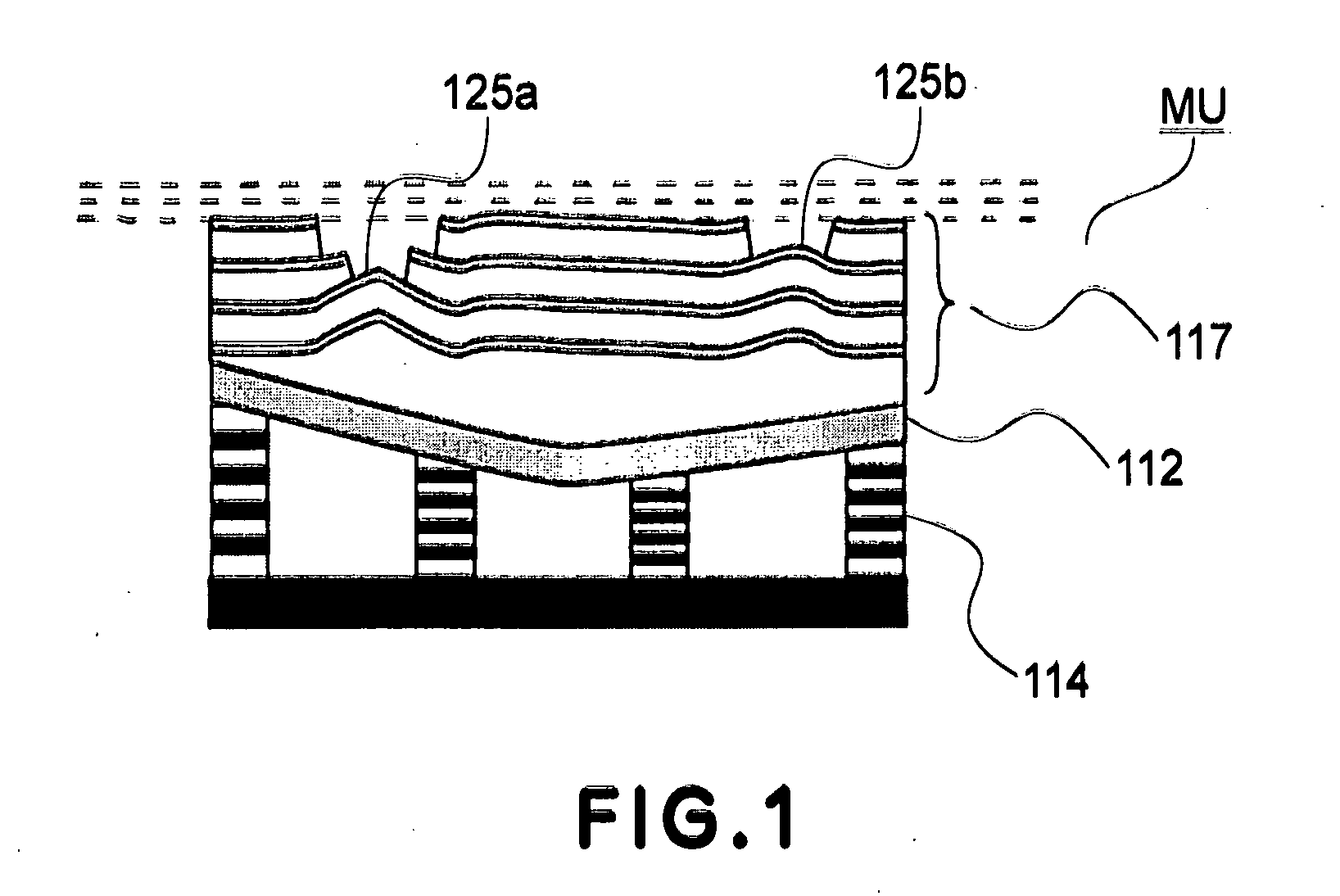
[0068]FIG. 1 is a schematic and sectional view of a main portion of a mirror unit MU according to a first embodiment of the present invention. FIGS. 14 and 15A-15C are schematic and sectional views, respectively, for explaining various states of a mirror unit (multilayered film mirror) MU according to the first embodiment, during the production process thereof.

[0069]FIG. 16 is a flow chart for explaining a method of producing a mirror unit according to the present invention. Here, FIGS. 15A-15C are sectional views of the mirror unit MU each corresponding to a certain stage in the procedure shown in FIG. 16.

[0070] The mirror unit MU as shown in FIGS. 1 and 15C is in the state in which deformation of a substrate 112 has been adjusted by means of an actuator 114 and coating milling means (film removing means) and thus the adjustment has been completed.

[0071] In this embodiment, one surface of the substrate 112 is a reflection surface on which a multilayered film 117 is...

embodiment 2

[Embodiment 2]

[0095]FIGS. 17A-17D are schematic and sectional views of a main portion of a mirror unit MU according to a second embodiment of the present invention. Among these drawings, FIG. 17A depicts the state in which deformation amounts at various points on a multilayered film 17 have been measured. FIG. 17B depicts the state in which, by approximating the deformation amounts with a lower-order periodic function, an approximation curve 119 has been determined. FIG. 17C depicts the state in which deformation of a substrate 112 has been carried out in accordance with the function of approximation curve 119. In the state of FIG. 17C, lower order deformation being larger than the period of mirror surface size has been corrected by use of substrate deforming means 113. FIG. 17D depicts the state in which higher order deformation not corrected by the substrate deforming means 114 has been corrected by means of a coating milling process. In the state of FIG. 17D, deformation having a...

embodiment 3

[Embodiment 3]

[0097]FIGS. 18A-18D are schematic and sectional views of a main portion of a mirror unit MU according to a third embodiment of the present invention. In this embodiment, thirteen (13) piezoelectric devices 114 are disposed in a radial direction of the mirror, such that correction with respect to smaller wavelength as compared with the second embodiment of FIGS. 17A-17D, that is, correction of as phase of a period length at least greater than a half of the mirror size is carried out by use of the substrate deforming means.

[0098] Thus, in accordance with this embodiment of the present invention, correction of a phase of a period length at least greater than a half of the mirror size is carried out on the basis of substrate deforming means, while deformation of a period which is length shorter than it (e.g. deformation of a period length not greater than 1 / 10) is corrected by coating milling.

[0099] Here, FIG. 18A depicts the state in which deformation amounts at various...


PUM

PropertyMeasurementUnit
wavelengthaaaaaaaaaa

Abstract

Disclosed is a mirror unit and a method of producing the same. In one preferred form of the present invention, the mirror unit includes (i) a mirror with a multilayered film formed on a substrate, the multilayered film having two materials periodically laminated in layers on the substrate, and (ii) a substrate deforming device for producing deformation of a shape of the substrate of the mirror, wherein, in the multilayered film, the number of laminated layers in a predetermined region of the substrate differs from that in another region of the substrate. A mirror unit producing method according to another preferred from of the present invention includes (a) forming a multilayered film on a substrate, the multilayered film having two materials periodically laminated in layers on the substrate, (b) providing substrate deforming means in association with the substrate, the deforming means having a function for producing deformation of the shape of the substrate, and (c) partially removing the multilayered film.

Description

FIELD OF THE INVENTION AND RELATED ART [0001] This invention relates to a mirror unit and an exposure apparatus having the same. More particularly, the invention concerns a mirror system suitably usable in an X-ray exposure apparatus, an EUV exposure apparatus or an X-ray microscope, for example. [0002] Lithographic printing (exposure) methods for manufacture of semiconductor devices having an extraordinarily fine circuit pattern such as semiconductor memory or logic circuit include a reduction projection exposure method using ultraviolet rays as printing light. [0003] The linewidth size of a smallest pattern that can be transferred by reduction projection exposure is proportional to the wavelength of light used for the pattern transfer, and it is inversely proportional to the numerical aperture of a projection optical system used. For this reason, light of very short wavelength is used as the light for transferring a fine circuit pattern. Examples are i-line (wavelength 365 nm) emi...

Claims


Application Information

Patent Timeline
Patent Type & Authority Applications(United States)
IPC IPC(8): G21K1/06G02B5/08G02B26/08G03F7/20G21K5/00G21K5/02H01L21/027
CPCG02B26/0825G21K1/062Y10S359/90
Inventor YAMAMOTO, TAKESHIMIYAKE, AKIRA
Owner CANON KK
Why Eureka
Try Eureka