Imaging lens

Active Publication Date: 2005-10-27
NIDEC COPAL CORPORATION
View PDF4 Cites 11 Cited by
  • Summary
  • Abstract
  • Description
  • Claims
  • Application Information

AI Technical Summary

Benefits of technology

[0008] The present invention overcomes the problems of the conventional technology described above and provides an imaging lens with superior optical properties, suited for use in portable telephones and portable information terminals, that uses a very simple three-group three-piece structure and provides a compact, thin, light-weight design that can be used with solid-state imaging elements of 1,000,000 pixels or more.
[0009] An imaging lens according to the present invention includes, in sequence from an object side to an image surface side: an aperture stop with a predetermined aperture diameter; a biconvex first lens with convex surfaces facing the object side and the image surface side having a positive refractive power; a meniscus-shaped second lens with a concave surface facing the object side having a negative refractive poser; and a meniscus-shaped third lens with a convex surface facing the object side having a positive refractive power. By providing the first lens and the third lens with a positive refractive power and the second lens with a negative refractive power make it possible to reduce the total length of the lens system while maintaining an appropriate back focus. As a result, a compact and thin imaging lens can be provided while maintaining desired optical properties.
[0010] In the structure described above, the second lens and the third lens can be formed with the surfaces on both the object side and the image surface side being aspherical surfaces. With this structure, various aberrations can be effectively corrected, thus providing an imaging lens suited for high-density solid-state imaging elements.

Problems solved by technology

With these triplet-type imaging lenses, however, it is difficult to provide back focus relatively long, beside keeping the exit pupil away from the image surface, and providing a very compact design with a wide viewing angle.

Method used


Image

  • Imaging lens
  • Imaging lens
  • Imaging lens

Examples


first embodiment

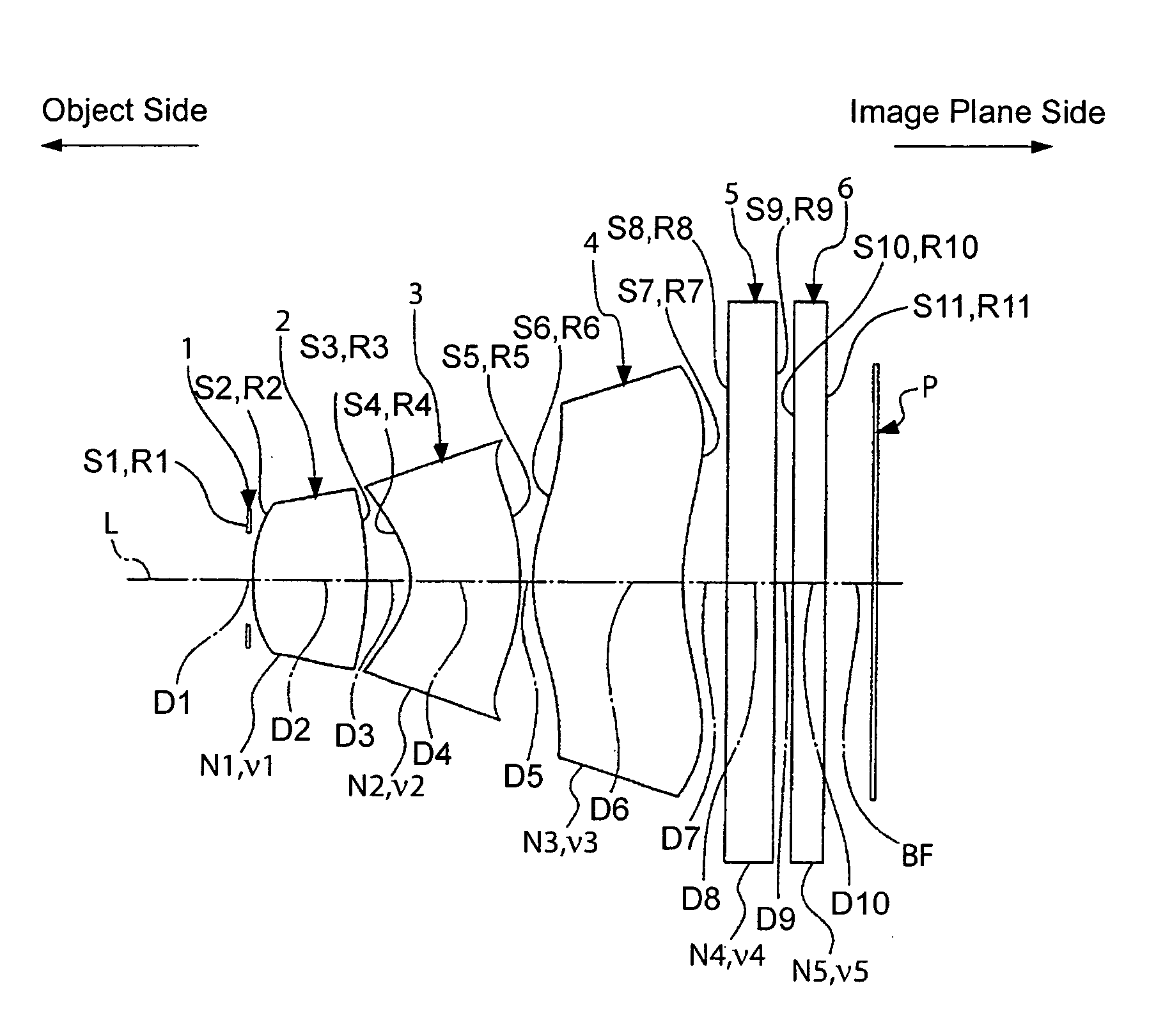
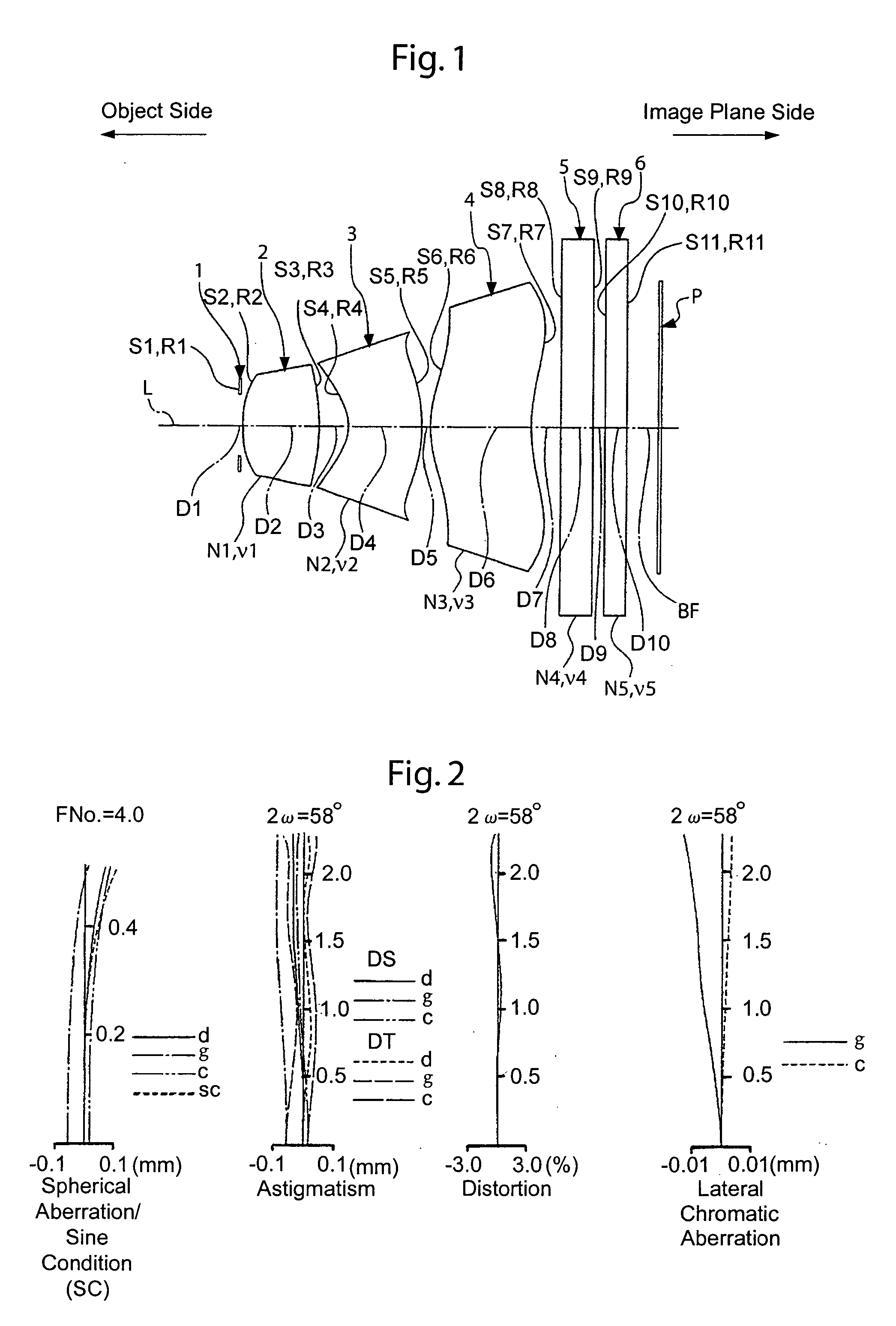
[0048] The basic structure of a lens system is shown in FIG. 1. The various specifications are shown in Table 1, the various numerical data (settings) are shown in Table 2, and numerical data relating to aspherical surfaces are shown in Table 3.

[0049] In this embodiment, the numerical data for each condition is as follows: (1) TL / f=5.79 / 4.10=1.41; (2) v1=70.4; (3) (D3+D5) / f=(0.41+0.13) / 4.1=0.13.

TABLE 1Object Distance700Angle of View58°(mm)(2 ω)Focal Length f (mm)4.1Total Length TL of Lens System 5.79(Front Surface of Aperture Stop toImage Surface)(Air Conversion Distance)(mm)F Number4.0Back Focus 1.41(Air Conversion)(mm)

[0050]

TABLE 2CurvatureradiusDistanceIndex of RefractionAbbeSurface(mm)(mm)(line d)numberS1R1∞Aperture StopD10.05S2R21.893D21.12N11.48749ν170.4S3R3−4.187D30.41S4*R4−0.981D41.17N21.50914ν256.4S5*R5−2.397D50.13S6*R62.114D61.50N31.50914ν356.4S7*R73.019D70.45S8R8∞D80.30N41.51633ν464.1S9R9∞D90.20S10R10∞D100.30N51.51633ν564.1S11R11∞BF0.40

*aspherical surface

[0051]

TABLE ...

second embodiment

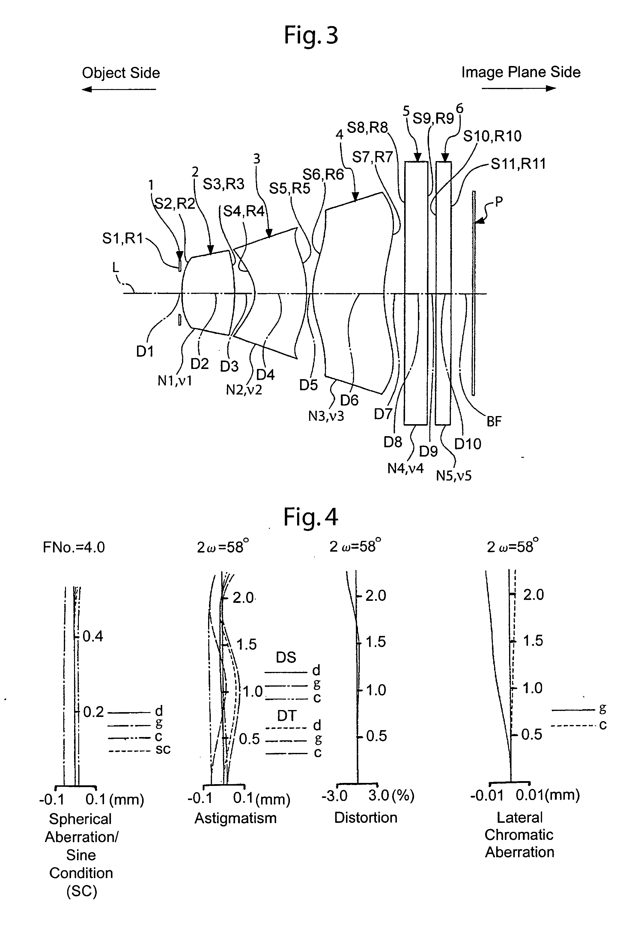
[0053] The basic structure of a lens system is shown in FIG. 3. The main specification data are shown in Table 4, the various numerical data (settings) are shown in Table 5, and numerical data relating to aspherical surfaces are shown in Table 6.

[0054] In this embodiment, the numerical data for each condition is: (1) TL / f=6.05 / 4.30=1.41; (2) v1=70.4; (3) (D3+D5) / f=(0.43+0.10) / 4.3=0.12.

TABLE 4Object Distance700Angle of View58°(mm)(2 ω)Focal Length f (mm)4.3Total Length TL of Lens System 6.05(Front Surface of Aperture Stop to Image Surface)(Air Conversion Distance)(mm)F Number4.0Back Focus 1.64(Air Conversion)(mm)

[0055]

TABLE 5CurvatureradiusDistanceIndex of RefractionAbbeSurface(mm)(mm)(line d)numberS1R1∞Aperture StopD10.05S2R22.152D21.15N11.48749ν170.4S3R3−3.497D30.43S4*R4−0.954D41.15N21.50914ν256.4S5*R5−2.281D50.10S6*R62.094D61.53N31.50914ν356.4S7*R72.881D70.45S8R8∞D80.45N41.51633ν464.1S9R9∞D90.20S10R10∞D100.30N51.51633ν564.1S11R11∞BF0.40

*aspherical surface

[0056]

TABLE 6Aspherica...

third embodiment

[0058] The basic structure of a lens system is shown in FIG. 5. The main specification data are shown in Table 7, the various numerical data (settings) are shown in Table 8, and numerical data relating to aspherical surfaces are shown in Table 9.

[0059] In this embodiment, the numerical data for each condition is: (1) TL / f=5.44 / 3.75=1.45; (2) v1=70.4; (3) (D3+D5) / f=(0.49+0.10) / 3.75=0.16.

TABLE 7Object Distance700Angle of View65 °(mm)(2 ω)Focal Length f (mm)3.75Total Length TL of Lens System 5.44(Front Surface of Aperture Stopto Image Surface)(Air Conversion Distance)(mm)F Number2.8Back Focus 1.70(Air Conversion)(mm)

[0060]

TABLE 8CurvatureradiusDistanceIndex of RefractionAbbeSurface(mm)(mm)(line d)numberS1R1∞Aperture StopD10.05S2R21.934D21.00N11.48749ν170.4S3R3−38.00D30.49S4*R4−1.038D40.94N21.50914ν256.4S5*R5−1.465D50.10S6*R61.920D61.16N31.50914ν356.4S7*R72.108D70.50S8R8∞D80.45N41.51633ν464.1S9R9∞D90.20S10R10∞D100.30N51.51633ν564.1S11R11∞BF0.50

*aspherical surface

[0061]

TABLE 9Aspheri...


PUM


Abstract

The present invention includes, from the object side to the image plane side, an aperture stop with a predetermined diameter, a first lens with a positive refractive power and a bi-convex shape with convex surfaces facing the object side and the image plane side, a second lens being formed as a meniscus shape with a concave surface facing the object side having a negative refractive power, and a third lens being formed as a meniscus shape with a convex surface facing the object side having a positive refractive power. By having a positive refractive power for the first lens and third lens and a negative refractive power for the second lens, a suitable back focus can be maintained while reducing the total length of the lens system. The imaging lens is thin and compact and has superior optical properties suited for mobile cameras mounted in portable telephones and PDAs.

Description

INCORPORATION BY REFERENCE [0001] The present application claims priority under 35 U.S.C. §119 to Japanese Patent Application No. 2004-131934 filed on Apr. 27, 2004. The content of the application is incorporated herein by reference in its entirety. BACKGROUND OF THE INVENTION [0002] The present invention relates to an imaging lens used in electronic imaging devices such as digital still cameras and digital video cameras that use solid-state imaging elements such as CCDs and CMOS. More specifically, the present invention relates to an imaging lens suitable for compact mobile cameras installed in portable telephones, portable information terminals (PDAs), and portable personal computers. [0003] Examples of conventional electronic imaging devices that use solid-state imaging elements such as CCDs include monitoring cameras and video cameras. These devices have been used primarily to capture moving images. For this reason, a high degree of performance was not required for these CCDs an...

Claims


Application Information

Patent Timeline
IPC IPC(8): G02B9/16G02B13/00G02B13/16G02B13/18
CPCG02B13/0035G02B13/18G02B13/16A47J27/05A47J2027/043Y10S220/912
Inventor NAGAI, YOUHEIABE, YASUHIKO
Owner NIDEC COPAL CORPORATION
Why Eureka
Try Eureka