Polymer based electro-optic scanner for image acquisition and display

an electro-optic scanner and polymer technology, applied in the field of image acquisition, can solve the problem of not capitalizing on this technology, and achieve the effects of easy prediction and control of exact location, maximum scanning frequency, and no image quality issu

Inactive Publication Date: 2005-10-27
UNIV OF WASHINGTON
View PDF6 Cites 31 Cited by
  • Summary
  • Abstract
  • Description
  • Claims
  • Application Information

AI Technical Summary

Benefits of technology

[0016] Another feature of embodiments of the present invention is that scanning is accomplished via changing the Bragg wavelength using electrical means rather than using a moving waveguide. This means that the illuminating light spot is not dependent on the dynamics of the waveguide. As a result it is easy to predict and control the exact location of the illuminated spot, making image quality not an issue. Also, the maximum scanning frequency is increased, sensitivity to external vibration and thermal variations is reduces, and field of view (FOV) is improved.
[0017] Another feature of embodiments of the present invention is its small size and flexibility. For example, in one embodiment the scope is has at least two dimensions of less than approximately on millimeter (1 mm) in diameter and has a tip deflection capability of 900 or greater in a single plane in either forward / backward or side to side direction. A significantly smaller and more flexible endoscope will advance the burgeoning field of minimally invasive medical techniques. A smaller scope also will allow doctors to see within body cavities that were previously inaccessible using conventional equipment. Also, a smaller scope provides more space for biopsy forceps, grasping forceps, surgical scissors, etc, and could make unsedated endoscopy procedures more probable. Without having to use sedation and analgesia during endoscopy reduces the risk of complications for many individuals in whom intravenous sedation is undesirable. The patients also avoid the prolonged recovery intervals due to the medications.
[0018] Another feature of embodiments of the present invention is that it resolves some of the problems with mechanical systems, such as mechanical fatigue, nonlinear dynamic effects at large fields of view (FOV), mechanical instability (no feedback, prompt to ambient vibration), signal drift, and fixed and low spatial resolution. For example, high scanning speeds (gigahertz range) increase spatial resolution in that it provides more lines per scan. SVGA image or greater resolution is easily obtained without increasing the overall design size. In embodiments, the resolution may be much greater than the currently available highest resolution endoscopes that have approximately 850,000-pixels.
[0019] Another feature of embodiments of the present invention is the ability to create a large field of view (FOV), such as greater than approximately ninety degrees (>90°) and a variable FOV. This is made possible by the fact that the input voltage to the beam deflectors (or electrical charge applied to the electro-optic polymer) will electronically control the scanning angle.
[0020] Another feature of embodiments of the present invention is the ability to transmit multiple wavelengths and variable zoom without loss of resolution (large depth of field). This is made possible by the broadband frequency response and voltage control of the electro-optic actuators, such as, for example, actuators made of a material that can be manipulated mechanically by an applied electromagnetic field, for light beam deflection. The focus adjustment procedure is significantly simplified due to the voltage control beam deflector, thus ensuring speedy observation. Optical magnification is also simplified due to the fact that the zoom-in and zoom-out functions are now controlled by the displacement and the line resolution of the voltage controlled beam deflectors.
[0021] The use of MEMS fabrication processes also offers advantages in that it allows for the integration of light sources, scanners, sensors, detectors, and electronics on a single chip configuration. This reduces the overall size and the power consumption of the system, while improving the signal to noise ratio, bandwidth and image quality. Batch processing also enables the production of a high quality product at low cost. This opens the door for design of disposable surgical imaging devices.

Problems solved by technology

Yet, to date, there has been no capitalization on this technology, to enhance the performance of endoscopes, for example.

Method used


Image

  • Polymer based electro-optic scanner for image acquisition and display
  • Polymer based electro-optic scanner for image acquisition and display
  • Polymer based electro-optic scanner for image acquisition and display

Examples


Embodiment Construction

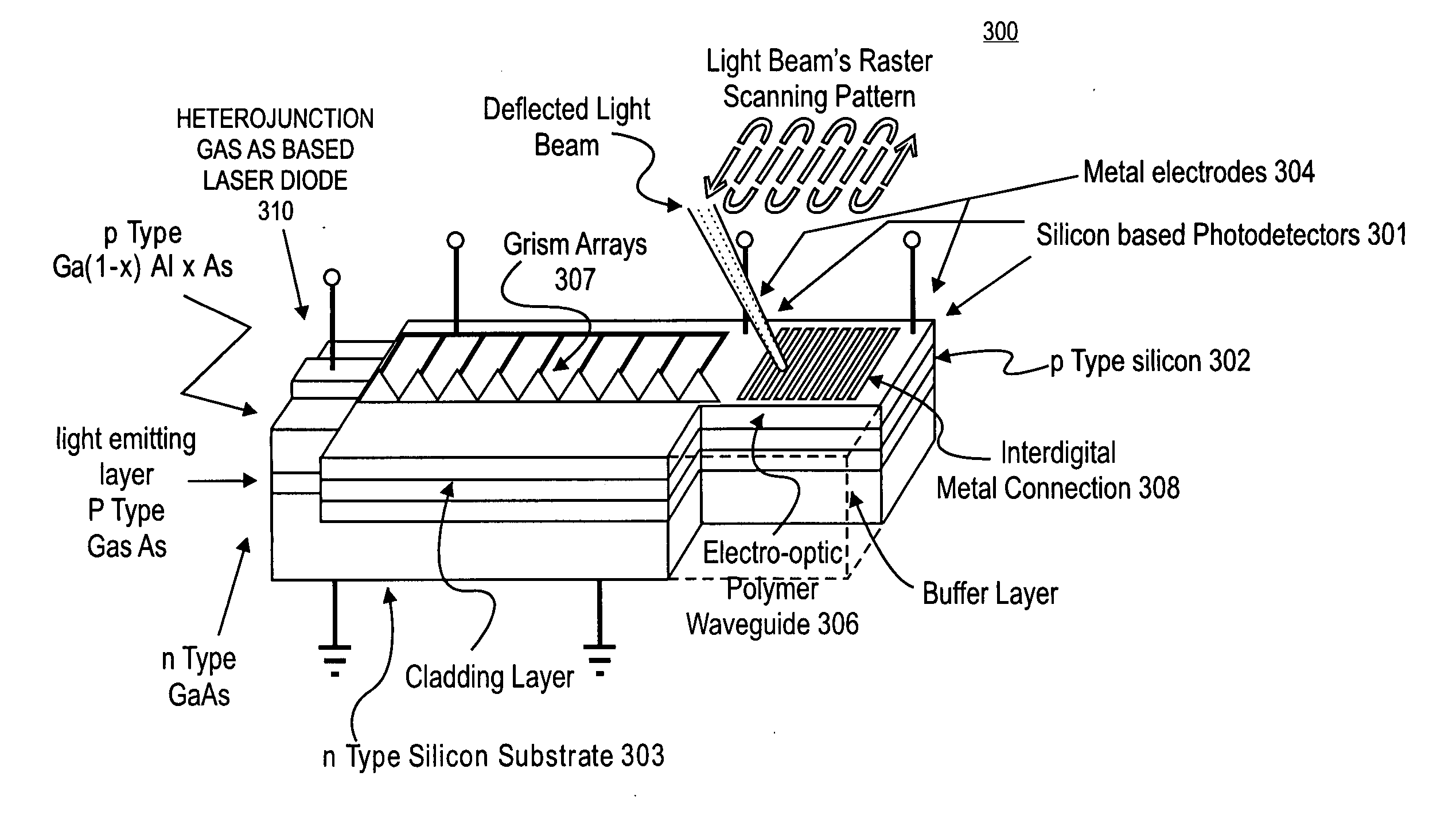
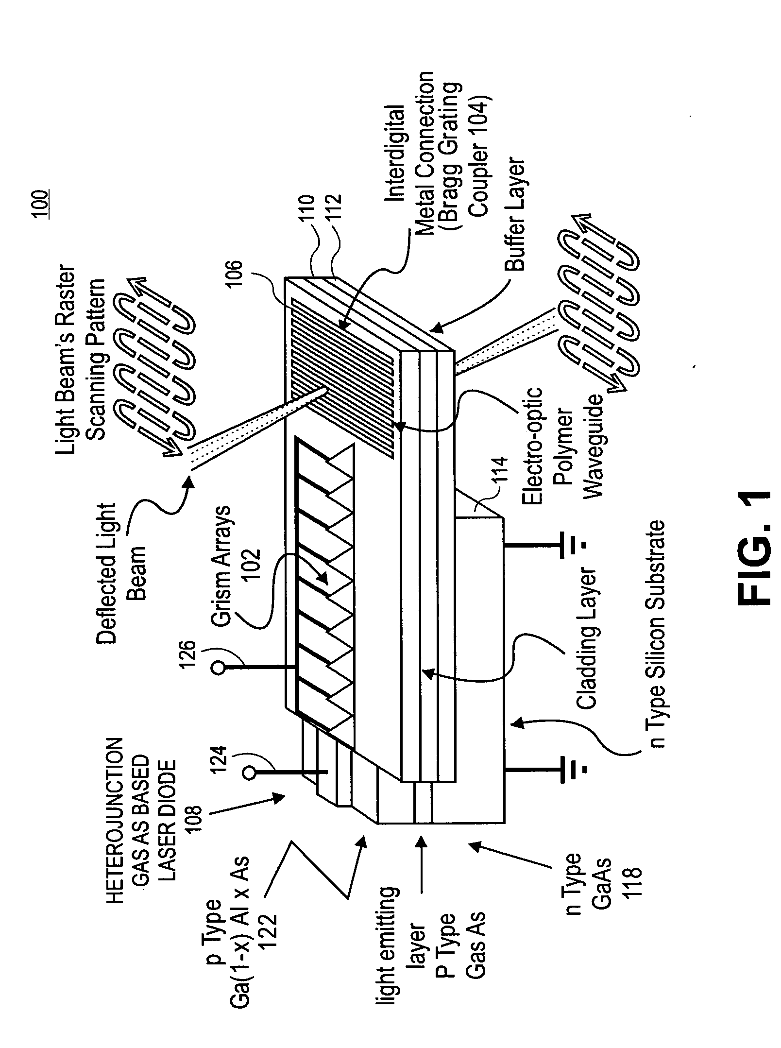
[0033]FIG. 1 is a cross-section diagram of a two-dimensional electro-optic scanner 100 according to an embodiment of the present invention. In the illustrated embodiment, the scanner 100 includes an electro-optic waveguide 102 having a cascaded horizontal beam deflector array 104 and a Bragg grating coupler 106 disposed thereon. The example horizontal beam deflector array 104 includes nine individual horizontal beam deflectors, each of which includes a prism and a transmission grating disposed on the hypotenuse of the prism.

[0034] In the illustrated embodiment, the electro-optic scanner 100 is a multi-layer structure. The illustrated scanner 100 includes a first a layer 106, which is a layer of electro-optic polymer, a second layer 110, which is a layer of optical material with slightly lower index of refraction n than the index of refraction of the layer 106 of electro-optic polymer, a third a layer 112, which is a layer of optical material that serves as buffer layer to prevent l...


PUM

PropertyMeasurementUnit
core diameteraaaaaaaaaa
diameteraaaaaaaaaa
diameteraaaaaaaaaa

Abstract

According to embodiments of the present invention, an ultra high speed miniature image acquisition system based on a scanning light beam for use with clinical endoscopic imaging applications, for example.

Description

CROSS REFERENCE TO RELATED APPLICATIONS [0001] This application claims the benefit of U.S. Provisional Application No. 60 / 548,930, filed Mar. 1, 2004.BACKGROUND [0002] 1. Field [0003] Embodiments of the present invention relate to image acquisition and, in particular, to flexible scopes for image acquisition. [0004] 2. Discussion of Related Art [0005] Flexible scopes are commonly used in medical applications to look inside the human body to check the status of such organs as lungs, intestines, and colon, for example. Presently available flexible scope designs use either a bundle of optical fibers, typically in a tube, and / or one or more cameras having an array of detectors to capture an image. [0006] All commercially available scopes suffer from a fundamental tradeoff between high image quality and small size, however. For example, the diameter of currently available flexible scopes cannot be reduced to smaller than the image size, and is limited by the individual pixel size of a ca...

Claims


Application Information

Patent Timeline
Patent Type & Authority Applications(United States)
IPC IPC(8): A61B1/005A61B1/04G02F1/065G02F1/295G02F1/335H04N5/225
CPCA61B1/00096A61B1/00183A61B1/0051A61B1/05A61B1/0684G02F1/295G02F1/2955G02F1/335G02F1/065
Inventor WANG, WEI-CHIHREINHALL, PER G.
Owner UNIV OF WASHINGTON
Why Eureka
Try Eureka