Eureka AIR delivers breakthrough ideas for toughest innovation challenges, trusted by R&D personnel around the world.

Method and apparatus for resonantly driving plasmon oscillations on nanowires

Inactive Publication Date: 2005-10-27
PLAIN SIGHT SYST
View PDF11 Cites 16 Cited by
  • Summary
  • Abstract
  • Description
  • Claims
  • Application Information

AI Technical Summary

Benefits of technology

[0010] These modes have the advantages that: the electric fields are even more intense than the original fields of the dielectric waveguide, the electric fields are most intense in a region which is accessible and the electric fields are not intensified within the dielectric waveguide, which can be advantageous in some applications where fields in the dielectric waveguide produce an undesirable background signal.

Problems solved by technology

Many schemes are currently used to achieve high fields but none are completely satisfactory.
However, the active volume is small which limits the accumulation of non-linear effects.
The active volume can be large in a long length of fiber, but it is difficult to introduce samples into the hollow core of the fiber.
However individual nanoparticles intercept only a very small part of an incident light beam which limits the electric field intensity.

Method used


Image

  • Method and apparatus for resonantly driving plasmon oscillations on nanowires
  • Method and apparatus for resonantly driving plasmon oscillations on nanowires
  • Method and apparatus for resonantly driving plasmon oscillations on nanowires

Examples


Embodiment Construction

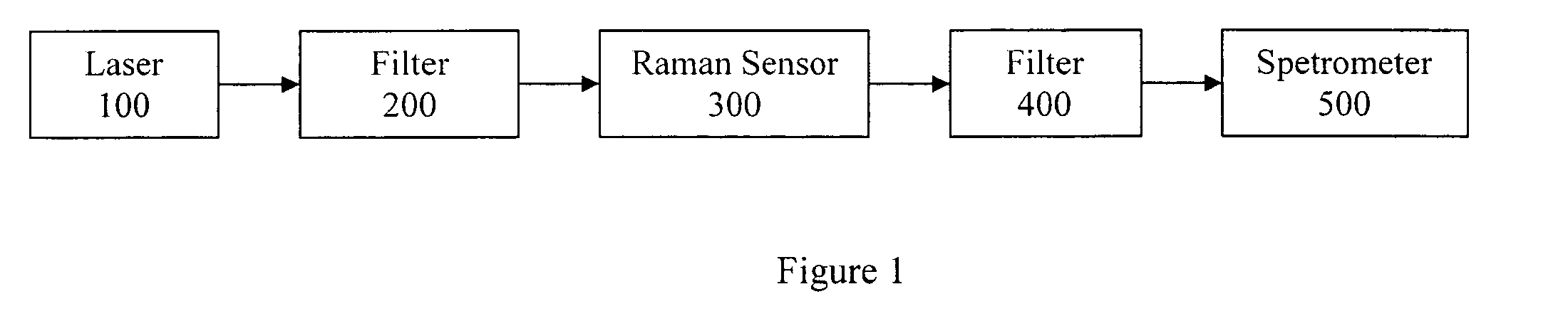
[0027] Turning now to FIG. 1 there is illustrated a block diagram of a Raman spectroscopy system 10 in accordance with an embodiment of the present invention. The Raman spectroscopy system 10 comprises a laser 100, a first filter 200, a Raman sensor 300, a second filter 400, and a spectrometer 500. In accordance with an aspect of the present invention, the Raman sensor 300 is used to generate intense optical fields. Typically the Raman sensor consists of a lens to concentrate the laser light to a spot with volume of order λ3. There are many possible applications and many possible realizations of the geometry. For example, in Raman scattering, embodiments of the invention can be used to create intense electric fields which then generate Raman scattered light from a sample. The scattered light can then be analyzed to determine the composition of the sample.

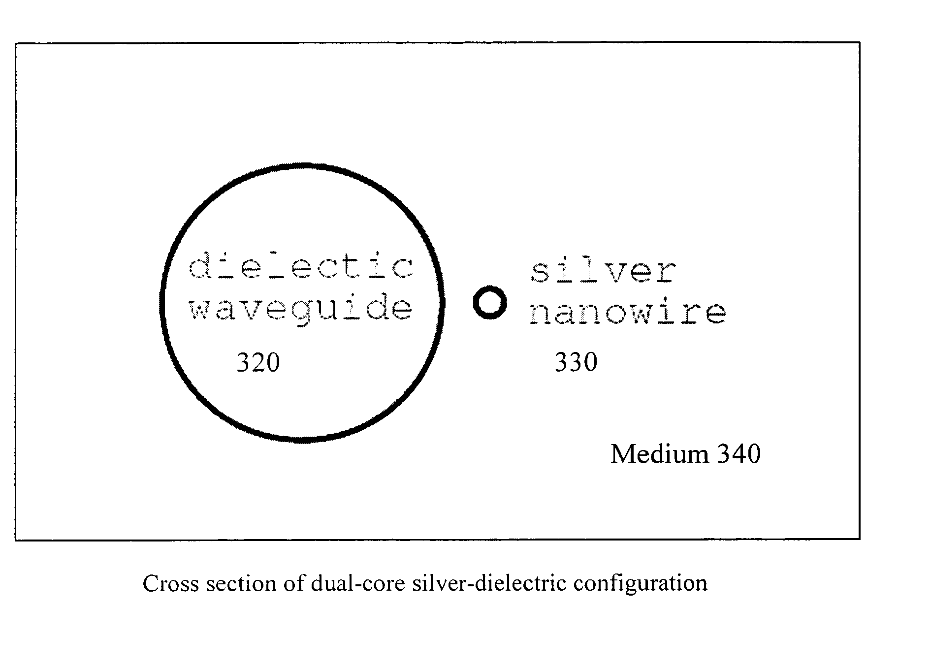
[0028] In accordance with an exemplary embodiment of the present invention, FIGS. 2 and 3 illustrate a novel Raman sensor 300 uti...


PUM


Abstract

Method and apparatus for resonantly driving a nanowire waveguide a dielectric waveguide core placed close to the nanowire waveguide, so that energy couples from the dielectric waveguide to the nanowire waveguide. The resonant coupling can be achieved by selecting the dielectric waveguide and the nanowire to support modes having substantially the same frequency ω and same longitudinal propagation constant β.

Description

RELATED APPLICATION [0001] This application claims priority benefit under Title 35, U.S.C. § 119(e) of provisional application No. 60 / 556,850, filed Mar. 26, 2004, which is incorporated by reference in its entirety.FIELD OF THE INVENTION [0002] The present invention is directed to the field of electric fields in Raman spectrography, and more particularly to extracting electromagnetic energy from a dielectric waveguide onto a nanowire. BACKGROUND OF THE INVENTION [0003] There are many applications where it would be advantageous to be able to produce very intense electric fields at high optical or infra-red frequencies, including, for example: second harmonic generation, third harmonic generation, parametric oscillation and amplification, intensity-dependent refractive index, saturable absorption, Brillouin scattering and Raman scattering. [0004] Many schemes are currently used to achieve high fields but none are completely satisfactory. For example, a lens can be used to concentrate ...

Claims


Application Information

Patent Timeline
IPC IPC(8): G02B6/10G02B6/122G02B6/26
CPCB82Y20/00G02B6/1226G02B6/107
Inventor CRUTCHFIELD, WILLIAM Y.
Owner PLAIN SIGHT SYST
Why Eureka
Eureka Blog
Learn More