Directional waveguide coupler for ABS reflected light

a directional waveguide and abs technology, applied in special recording techniques, instruments, record information storage, etc., can solve the problem of relative accuracy in measurement, and achieve the effect of improving the waveguide structure and accurate reading of light intensity

Active Publication Date: 2012-06-21
HEADWAY TECH INC
View PDF8 Cites 35 Cited by
  • Summary
  • Abstract
  • Description
  • Claims
  • Application Information

AI Technical Summary

Benefits of technology

[0012]One objective of the present invention is to provide an improved waveguide structure that enables back reflected light intensity from the ABS / medium interface to be measured for a more accurate reading of light intensity at the ABS and media in a TAMR scheme.

Problems solved by technology

However, this is a relatively inaccurate measurement since the percentage of light propogated from the light source away from the ABS may vary over time.
Furthermore, other factors influence the amount of light propogated through the waveguide toward the media such that the light intensity emanating from the light source near the back end of the waveguide does not necessarily correlate well to the light intensity proximate to the ABS.

Method used


Image

  • Directional waveguide coupler for ABS reflected light
  • Directional waveguide coupler for ABS reflected light
  • Directional waveguide coupler for ABS reflected light

Examples


first embodiment

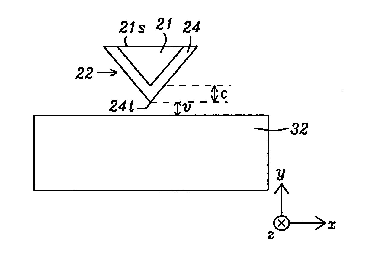
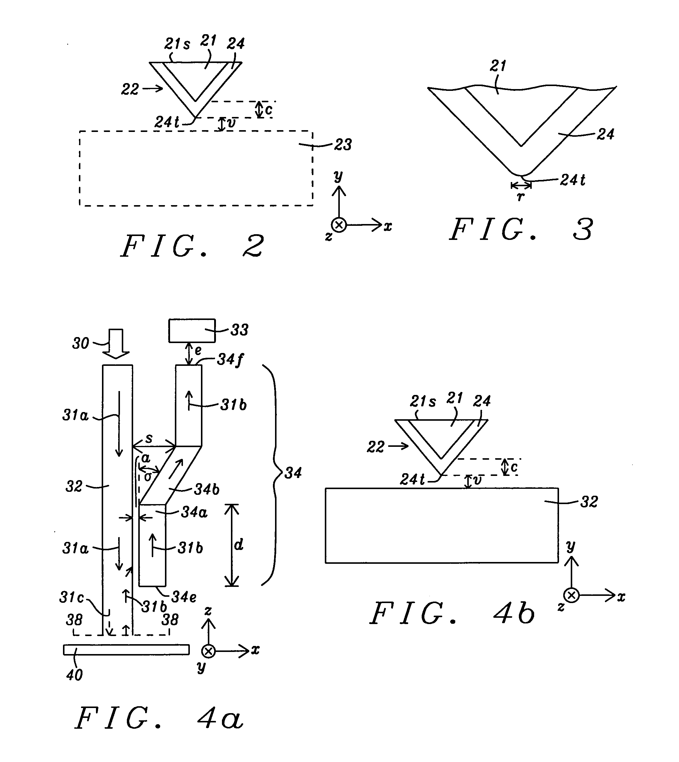
[0033]Referring to FIG. 4a, the present invention is depicted from a top view. Dielectric layers, EPG, and main pole are not illustrated in order to point out the features of the waveguide structure. There is a main waveguide 32 having a lengthwise dimension in a z-axis direction that is perpendicular to the plane of the medium 40 and to the ABS 38-38. Waveguide 32 serves to direct light 31a from a light source 30 towards the ABS 38-38. A substantial portion of light 31a is coupled to a near field device (not shown) which converts light into plasmon waves 31c that are transmitted the final distance to the ABS and produce a near field at the ABS and medium 40. In a preferred embodiment, the present invention employs an EPG 22 (FIG. 4b) as the near field device with a plasmon layer as described previously with respect to FIG. 2. The EPG has one end at the ABS 38-38 and extends in a z-axis direction for a distance of about 1 to 1.5 microns. In the exemplary embodiment, waveguide 32 ter...

second embodiment

[0043]Referring to FIG. 5, a TAMR waveguide structure is shown that comprises detection waveguides 34, 35 positioned on either side of the main waveguide 32 in a symmetrical configuration. The features of detection waveguide 34 are retained from the previous embodiment with the exception that the photo detector at the end 34f is designated as photo detector 33a. One concern with a single detection waveguide design as described in the previous embodiment is a slight distortion of the core (main) waveguide mode symmetry. However, symmetry may be maintained by adding a second detection waveguide on the opposite side of the main waveguide. In the exemplary embodiment, the detection waveguides 34, 35 terminate at essentially the same distance from the ABS as the main waveguide 32. Furthermore, the second detection waveguide 35 comprises three sections 35a, 35b, and 35c that are symmetrically positioned on the opposite side of waveguide 32 with regard to sections 34a, 34b, 34c, respective...


PUM

PropertyMeasurementUnit
gap distanceaaaaaaaaaa
coupling lengthaaaaaaaaaa

Abstract

A waveguide structure for a TAMR head is disclosed wherein at least one detection waveguide is formed parallel to a main waveguide and located a gap distance therefrom. A light source transmits light into the main waveguide and towards an ABS/medium interface. A plasmon generator converts light from the waveguide into plasmon waves that are directed onto a magnetic medium. Back reflected light is captured by the main waveguide, partially diverted into a detection waveguide, and transmitted to a photo detector that measures light intensity (IB) which correlates closely to the plasmon wave intensity at the ABS/medium interface. A controller linked to the photo detector is employed to calculate IB as a function of ABS/medium spacing in a non-write condition and this relationship can be used to control and maintain a constant plasmon wave intensity at the ABS during a series of TAMR write processes with a plurality of media.

Description

RELATED PATENT APPLICATION[0001]This application is related to the following: Docket # HT09-003, Ser. No. 12 / 456,290, filing date Jun. 15, 2009; assigned to a common assignee and herein incorporated by reference in its entirety.FIELD OF THE INVENTION[0002]The invention relates to magnetic read / write heads based on thermally assisted magnetic recording (TAMR) and in particular to a TAMR head in which a coupling waveguide is provided on at least one side of a main waveguide to enable an improved measurement of light energy at the media interface with the air bearing surface (ABS) which means a more controlled heating gradient at the media for higher recording density.BACKGROUND OF THE INVENTION[0003]TAMR is expected to be one of the future generation of magnetic recording technologies that will enable recording at ˜1-10 Tb / in2 data densities. TAMR involves raising the temperature of a small region of a magnetic medium to near its Curie temperature where both of its coercivity and anis...

Claims


Application Information

Patent Timeline
Patent Type & Authority Applications(United States)
IPC IPC(8): G11B11/00
CPCG02B6/1226G02B6/125G02B6/2821B82Y20/00G11B5/3189G11B2005/001G11B2005/0021G11B5/314
Inventor SCHRECK, ERHARDMALETZKY, TOBIASJIN, XUHUIZHOU, YUCHUNTAKANO, KENICHISMYTH, JOE
Owner HEADWAY TECH INC
Why Eureka
Try Eureka