Waveguide-based wireless distribution system and method of operation

a wireless distribution and waveguide technology, applied in waveguides, transmission monitoring, high-level techniques, etc., can solve the problems of time distortion and fade of encoded data on radio frequencies, moderately better recovery of transmitted signals, and becoming increasingly difficult to provide reliable communications to users of higher-speed wireless data, voice and video services, etc., to achieve high-efficiency waveguide-based wireless distribution

Active Publication Date: 2009-10-20
WIRELESS EXPRESSWAYS
View PDF78 Cites 37 Cited by
  • Summary
  • Abstract
  • Description
  • Claims
  • Application Information

AI Technical Summary

Problems solved by technology

This is particularly the case where government regulations and industry standards limit transmit power to low levels.
Structure and object-induced multiple reflections of radio signals that concurrently arrive from two or more directions at a receiving antenna and can cause time distortion and fading of encoded data on radio frequencies that are presented to a receiver.
Receiver-based software processing of signals from multiple, co-located receiving antennas offers some improvement in signal quality, but obtains only moderately better recovery of a transmitted signal that has already suffered significant time delay spreading distortion, and amplitude distortion, in a reflecting, physically cluttered path taken by a signal.
It is becoming increasingly difficult to provide reliable communications to users of higher-speed wireless data, voice and video services when centralized antennas are employed due to amplitude attenuation and reflection delays suffered by wireless signals passing through walls, partitions, floors, stair wells, and other structures and objects typically found in buildings.
There is a continuing (and increasing) challenge to cover all required areas in a facility with sufficient and predictable signal strength and quality that will provide reliable communications in an environment of government regulations that limit the maximum output power of wireless transmitters.
Solving these wireless communications problems through improvements in wireless receiver sensitivity in the cited frequency range is increasingly challenging since receiver technology is close to reaching its theoretical limit of sensitivity in current system designs.
The use of high-speed digital signal processors is somewhat improving data recovery, but at a price of higher power source drain, which causes lower battery life in portable systems, complex software, and increased cost.
With restricted transmitter output power and limited receiver sensitivity, systems employing higher data rates and current system designs are restricted to a shorter operating range, thus requiring more radio transceivers to cover a given area, which incurs higher system costs and a greater risk of interference among radios in nearby areas that must share a common channel frequency.
Several of these factors combine to limit the communications range or economical deployment of these types of systems.
Although limited range is desirable in some instances, most wireless systems suffer from limited coverage and / or the ability to cover desired areas with defined signal strength and quality.
Incompatibilities among different types of radio devices operating in the same frequency band are also a growing problem, especially when base unit antennas for each must be located in close proximity, and nearby radio transmitters that share the same spectrum are operated at an elevated transmit power to be able to obtain maximum communications range through structures and other objects.
This type of leaky, linear radiator has a number of disadvantages at higher frequencies, however, due to the relatively high longitudinal signal attenuation inherent in a practical diameter of leaky coaxial cable.
This characteristic quickly limits its useable longitudinal and orthogonal coverage distance, especially at microwave frequencies.
Other disadvantages of leaky coaxial radiators include their lack of ability to vary their amount of coupling, i.e., leakage rate, along the length of the cable to compensate for linear loss in the cable, and their undesirable characteristic of radiating and receiving in a 360 degree zone orthogonal to the cable, and along its total length.
Full radial radiation is disadvantageous in most applications since the intended user is typically located, for example, beneath the cable.
Radiation upward from the cable, in this case, is wasted by absorption in the building's structure above, and also allows the possibility of intrusion from signals originating above the leaky line.
Radiation from a leaky cable in unwanted areas over and under which the cable passes is also undesirable, wasteful of signal power, and difficult to avoid since it is difficult to implement a leaky cable system that will selectively apply signal to specific zones, and not others.
As a result, coaxial cables, and any other types of signaling components designed for service in plenum spaces, must use special insulating materials in their construction, such as DuPont polytetrafluoroethylene (“Teflon®”), which causes radio frequency coaxial cables made from this type of material to be prohibitively expensive in many applications.
Because of these restrictions, presently available technology does not offer practical, efficient, hidden wireless distribution systems that are designed for applications in HVAC plenum spaces, nor are present wireless distribution systems designed to be placed out of sight in plenum spaces.

Method used


Image

  • Waveguide-based wireless distribution system and method of operation
  • Waveguide-based wireless distribution system and method of operation
  • Waveguide-based wireless distribution system and method of operation

Examples


Embodiment Construction

[0037]The disclosed subject matter includes various embodiments of a waveguide-based wireless distribution system shown in the above-listed drawings, where like reference numerals designate like parts and assemblies throughout the several views. Reference to various embodiments does not limit the scope of the claimed subject matter.

[0038]The terms “wireless” and “radio” are used synonymously throughout the Detailed Description to generally refer to any form of wireless, i.e., radio signal communication at any applicable frequency, unless a specific communication scheme and / or frequency is indicated (such as IEEE 802.11b, Bluetooth, etc.).

Waveguide System

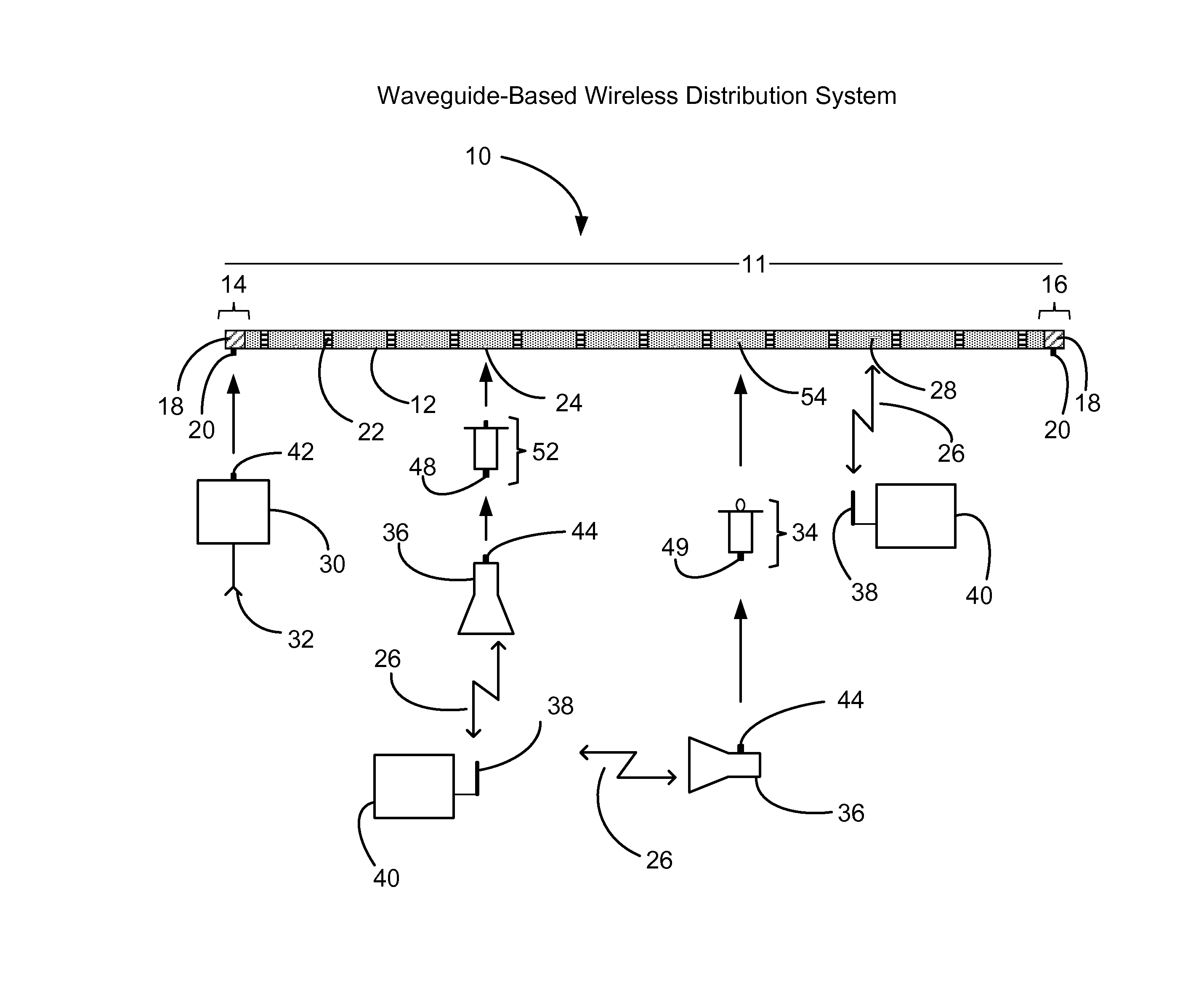
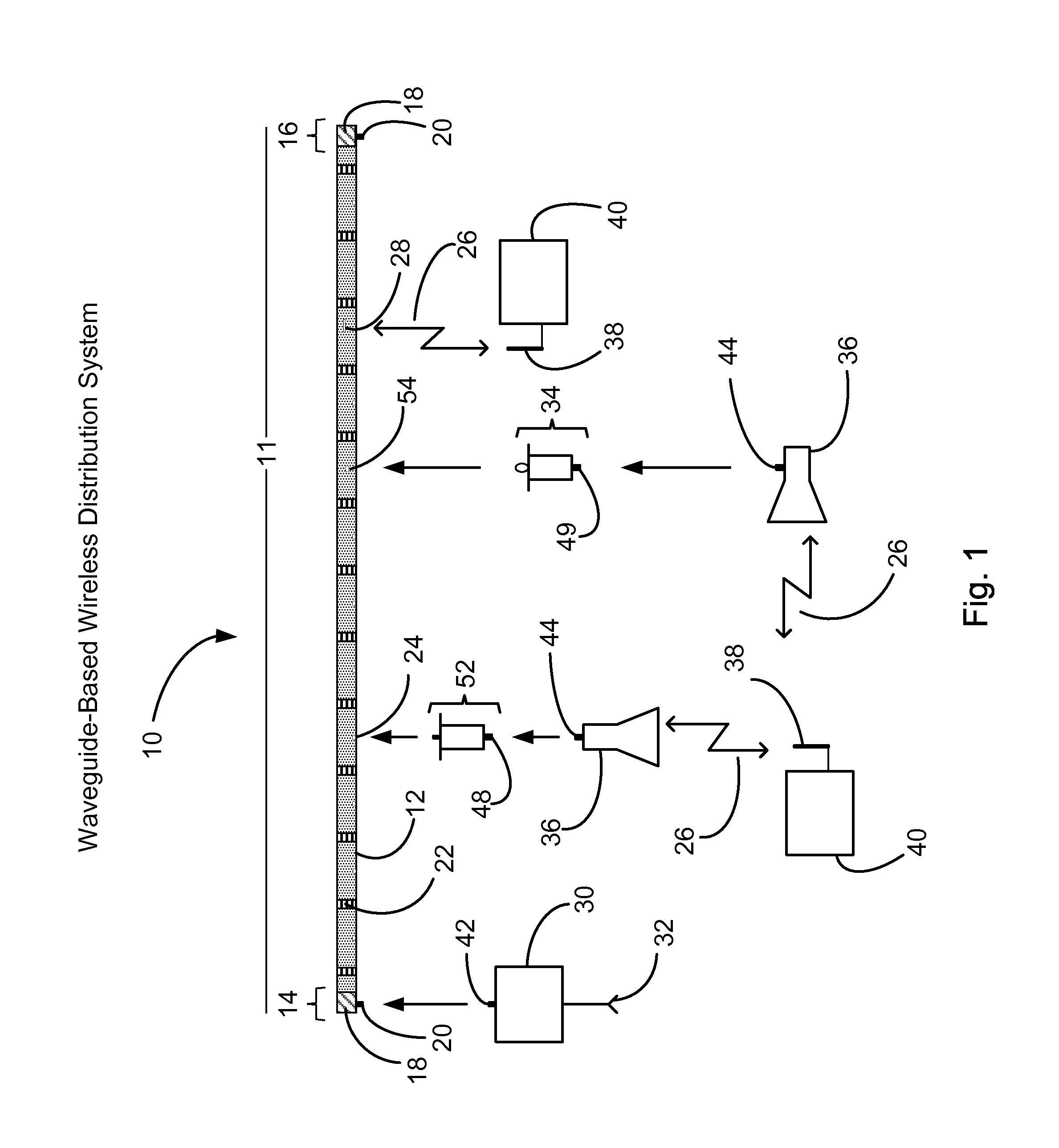
[0039]FIG. 1 illustrates an exemplary embodiment of a waveguide-based wireless distribution system 10 configured in accordance with aspects of the claimed subject matter in a predetermined bandpass frequency range. The waveguide-based wireless distribution system 10 comprises a waveguide 11, which is composed of one or more waveguide...


PUM


Abstract

The design and use of a simplified, highly efficient, waveguide-based wireless distribution system are provided. A low-loss waveguide is used to transport wireless signals from a signal source or sources to one or more receiver locations. One or more adjustable signal coupling devices partially insert into the waveguide at predetermined locations along the length of the system to provide variable, controlled extraction of one or more wireless signals. Low-loss impedance matching circuitry is provided between the waveguide coupling devices and output connectors to maintain high system efficiency. The system offers the capability of supplying signals of high strength and high quality to a large number of receivers in a wide wireless coverage area via a plurality of signal radiators. Some embodiments of the system are readily adaptable for wireless distribution service in HVAC plenum spaces. A system that combines the functions of fire extinguishing and waveguide wireless distribution is also disclosed.

Description

CROSS-REFERENCE TO RELATED PATENT APPLICATIONS[0001]This patent application claims the benefit of U.S. Provisional Patent Application No. 60 / 718,419, entitled “Waveguide Wireless Distribution System,” and filed Sep. 19, 2005.FIELD[0002]The present disclosure relates to wireless (radio) distribution systems, and more particularly to systems for distributing and gathering wireless signals in buildings, such as offices, factories, warehouses, schools, homes, and government facilities, and in open venues such as sports stadiums, parks, motorways and railways.DESCRIPTION OF THE RELATED ART[0003]This background information is provided in the context of a specific problem to which the disclosed subject matter in one or more of its aspects is applicable: the efficient distribution of wireless signals inside and outside offices or other buildings in which distances and structural impediments, or other objects, may otherwise diminish the strength and quality of wireless signals, and for the e...

Claims


Application Information

Patent Timeline
Patent Type & Authority Patents(United States)
IPC IPC(8): H04B7/00
CPCA62C35/60H01P3/12F16L3/23F16L3/26H01P3/127H01P5/103H01P5/12H01P5/18H01Q1/007H01Q1/2291H01Q1/44H01Q13/0233H01Q13/22H01Q21/0043A62C99/0018Y02D30/70H01P5/04H01Q19/12
Inventor BECKER, CHARLES D.
Owner WIRELESS EXPRESSWAYS
Why Eureka
Try Eureka