

Fuel cell stack
a fuel cell and stack technology, applied in the field of fuel cells, can solve the problems of low temperature and scarce air flow, and achieve the effects of preventing the decrease of voltage, preventing the decrease of the output of the whole stack, and small water produced at the cathode per unit area
- Summary
- Abstract
- Description
- Claims
- Application Information
AI Technical Summary
Benefits of technology
Problems solved by technology
Method used
Image

Examples
embodiment 1
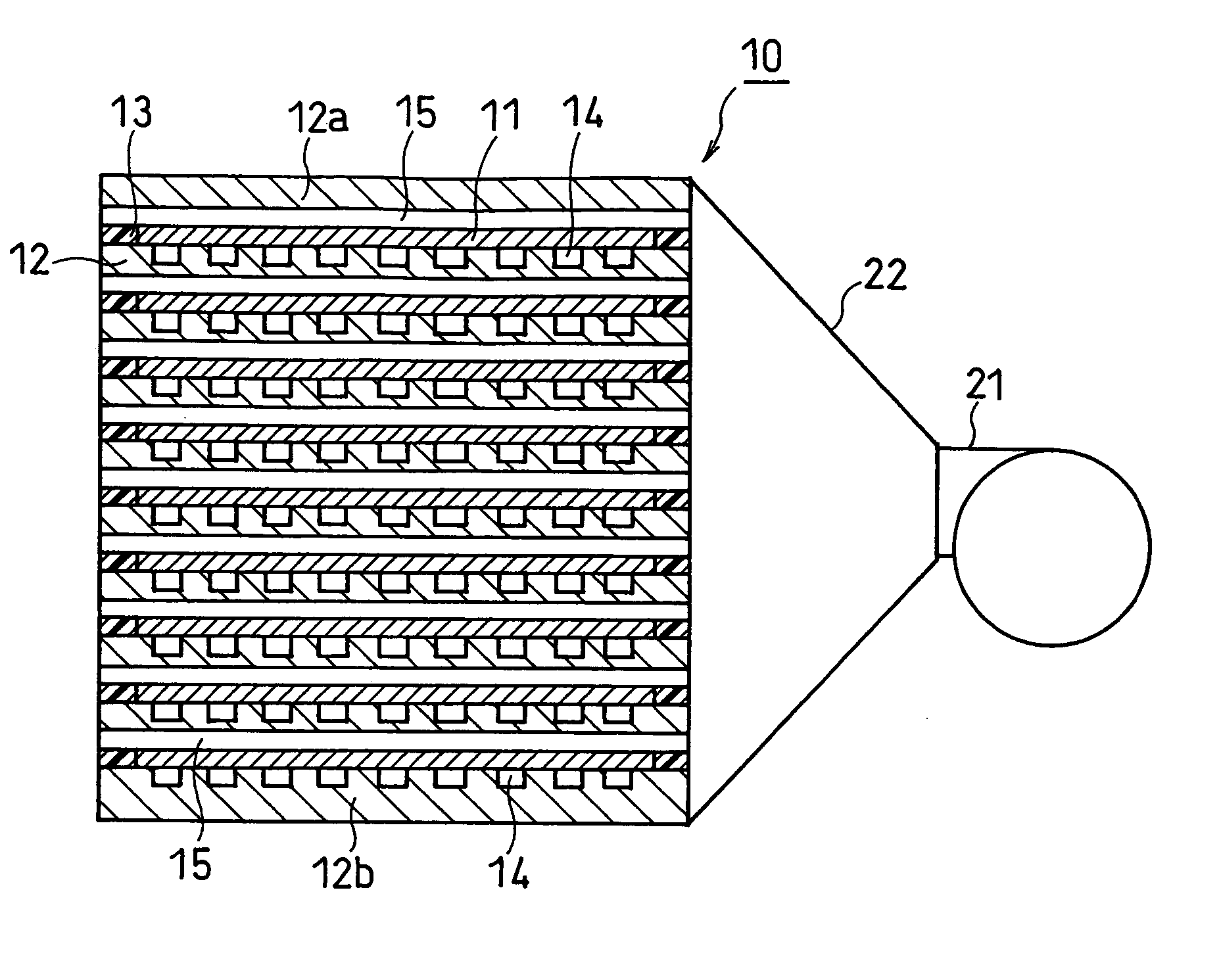
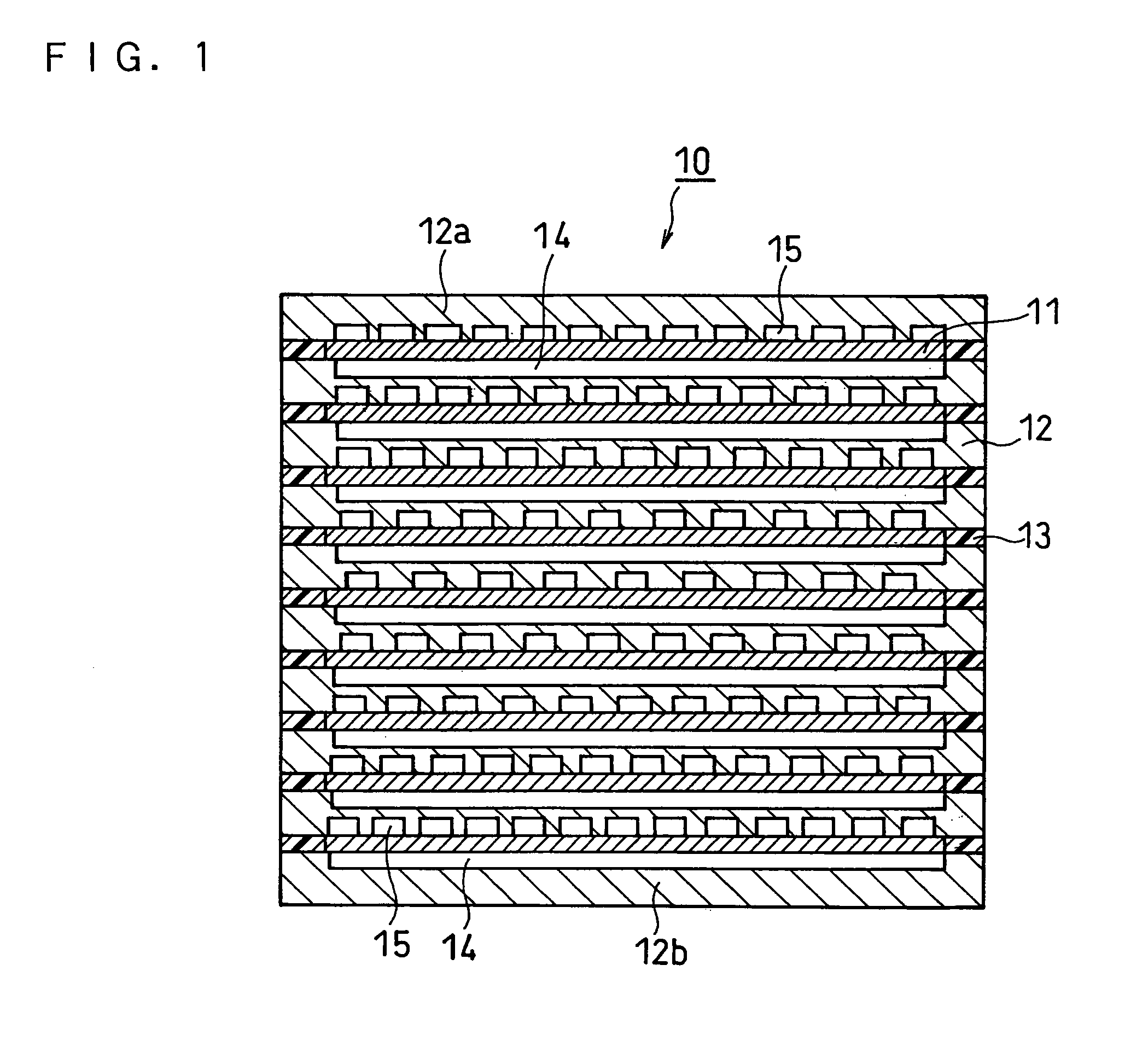
[0048]FIG. 1 is a schematic cross-sectional view of a fuel cell stack 10 according to this embodiment taken perpendicular to the flowing direction of air. FIG. 2 is a schematic cross-sectional diagram illustrating an arrangement of the fuel cell stack 10, an air-supplying device 21 and an air-introducing duct 22. The cross section of the fuel cell stack 10 in FIG. 2 is in parallel with the flowing direction of air. In this diagram, a single air-supplying device 21 and the inlet of a single fuel cell stack 10 are connected with an air-introducing duct 22. Although the cross section of the air-introducing duct 22 is increased toward the fuel cell stack 10 in FIG. 2, the shape of the duct is not limited thereto.
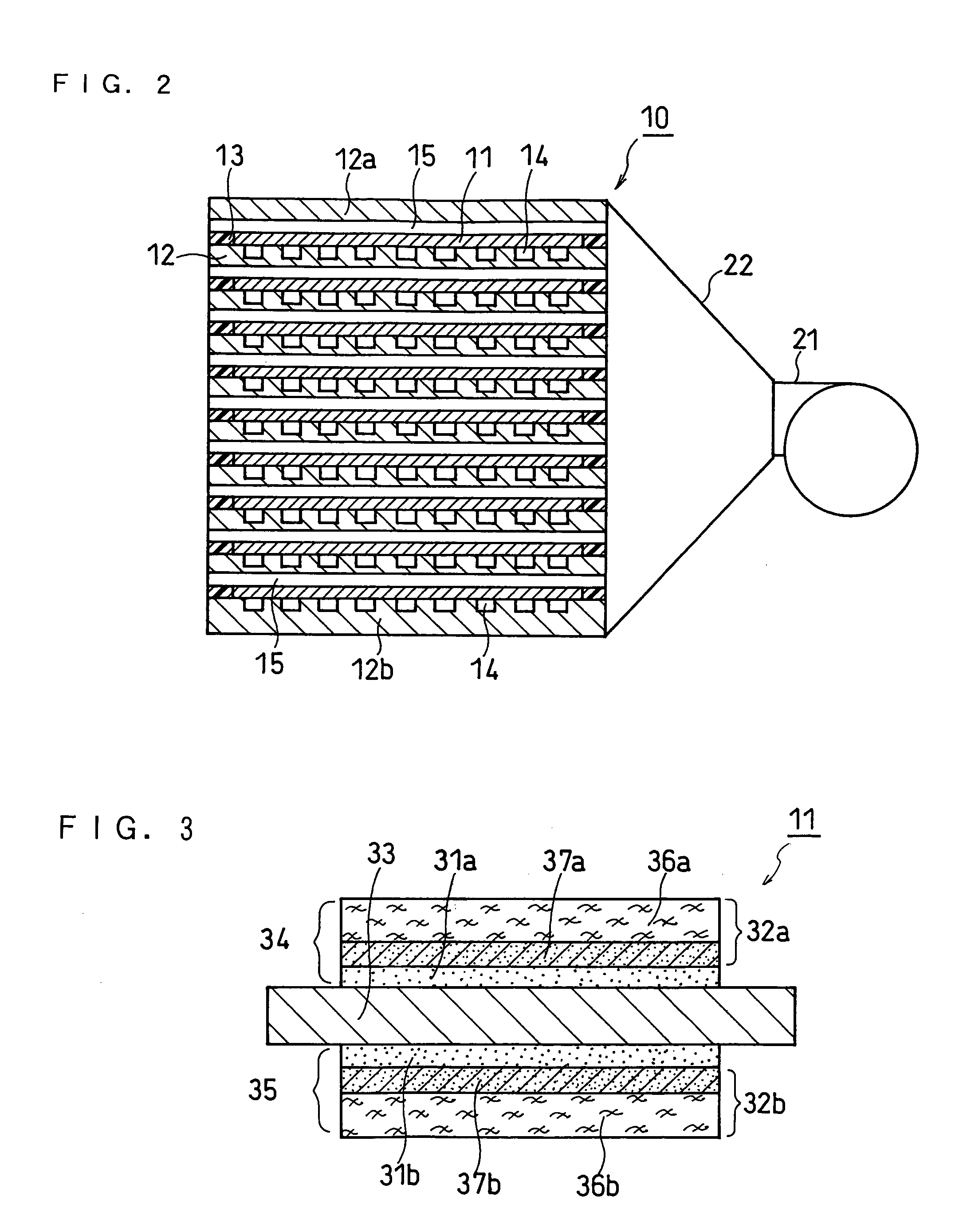
[0049] The fuel cell stack 10 is a stack comprising membrane electrode assemblies (MEAs) 11 and separators placed on both surfaces of each MEA 11. Insulating gaskets 13 are arranged on the peripheries of the MEAs 11. The gaskets 13 serve to prevent adjacent unit cells from shor...
embodiment 2
[0063] The fuel cell stack according to this embodiment has a structure identical to that of Embodiment 1 except that, instead of the cross-sectional area of the inlet side of the oxidant channel, the area of the cathode catalyst layer is the largest in the unit cells positioned at the ends of the stack.
[0064]FIG. 4 is a schematic vertical cross-sectional view of a fuel cell stack 40 according to this embodiment taken perpendicular to the flowing direction of air. The fuel cell stack 40 is a stack comprising membrane electrode assemblies (MEAs) 41 and separators placed on both surfaces of each MEA 41. Insulating gaskets 43 are arranged on the peripheries of the MEAs 41. The fuel cell stack 40 has nine unit cells stacked. Each single unit cell has the MEA 41 and a fuel channel 44 and an oxidant channel 45 arranged on both sides of the MEA 41. The structure of the MEA 41 is the same as that of Embodiment 1.
[0065] On one end of the fuel cell stack 40 is placed a separator 42a having ...
embodiment 3
[0070] The fuel cell stack according to this embodiment has a structure identical to that of Embodiment 1 except that, instead of the cross-sectional area of the inlet side of the oxidant channel, the thickness of the electrolyte membrane is the greatest in the unit cells positioned at the ends of the stack.
[0071] When the fuel cell stack comprising at least three unit cells stacked with separators interposed therebetween is used to construct a DMFC, it is important to take into account the transport of methanol and water due to the crossover phenomenon in the designing process.
[0072] First, the transport of methanol due to the crossover phenomenon is explained.
[0073] The transport of methanol is considered to be caused mainly by two factors: (1) molecular diffusion of methanol and (2) electrochemical transport of protons. The former is a diffusion phenomenon based on the difference of the methanol concentration on the interface between the electrolyte membrane and the anode and ...
PUM
| Property | Measurement | Unit |
|---|---|---|
| voltage | aaaaa | aaaaa |
| voltage | aaaaa | aaaaa |
| voltage | aaaaa | aaaaa |
Abstract
Description
Claims
Application Information