
Fuel cell system

a fuel cell and system technology, applied in the field of fuel cell systems, can solve the problems of mea damage and degradation, reaction gas in one or more unit cells may sometimes be less than the amount needed, and achieve the effect of preventing efficient degradation of mea

Active Publication Date: 2014-07-15
TOYOTA JIDOSHA KK
View PDF25 Cites 1 Cited by
  • Summary
  • Abstract
  • Description
  • Claims
  • Application Information

AI Technical Summary

Benefits of technology

Prevents MEA degradation by accurately identifying anode gas shortages and allowing cathode gas shortages for self-heating, thus preventing unnecessary power generation cessation and enhancing startability at low temperatures.

Problems solved by technology

However, for some causes, a reactant gas in one or more unit cells may sometimes become lack of the amount of supply with respect to the needed amount.
However, since the unit cells are connected in series, even the unit cell being lack of the supply of the reactant gas is required to cause the flow of the same amount of electric current as the other normal unit cells.
Therefore, when the current is forced to flow in the unit cell lacking in the supply of the reactant gas, the following abnormal chemical reactions may occur.
In particular, the abnormal chemical reactions due to the supply shortage of the fuel gas cause damage and degradation of the MEA (Membrane Electrode Assembly).
When the fuel cell starts up at low temperature, in particular, starts up at a temperature below the freezing point, gas channels may be occluded by ice or water, and thereby the fuel gas may be insufficiently supplied to the fuel cell.
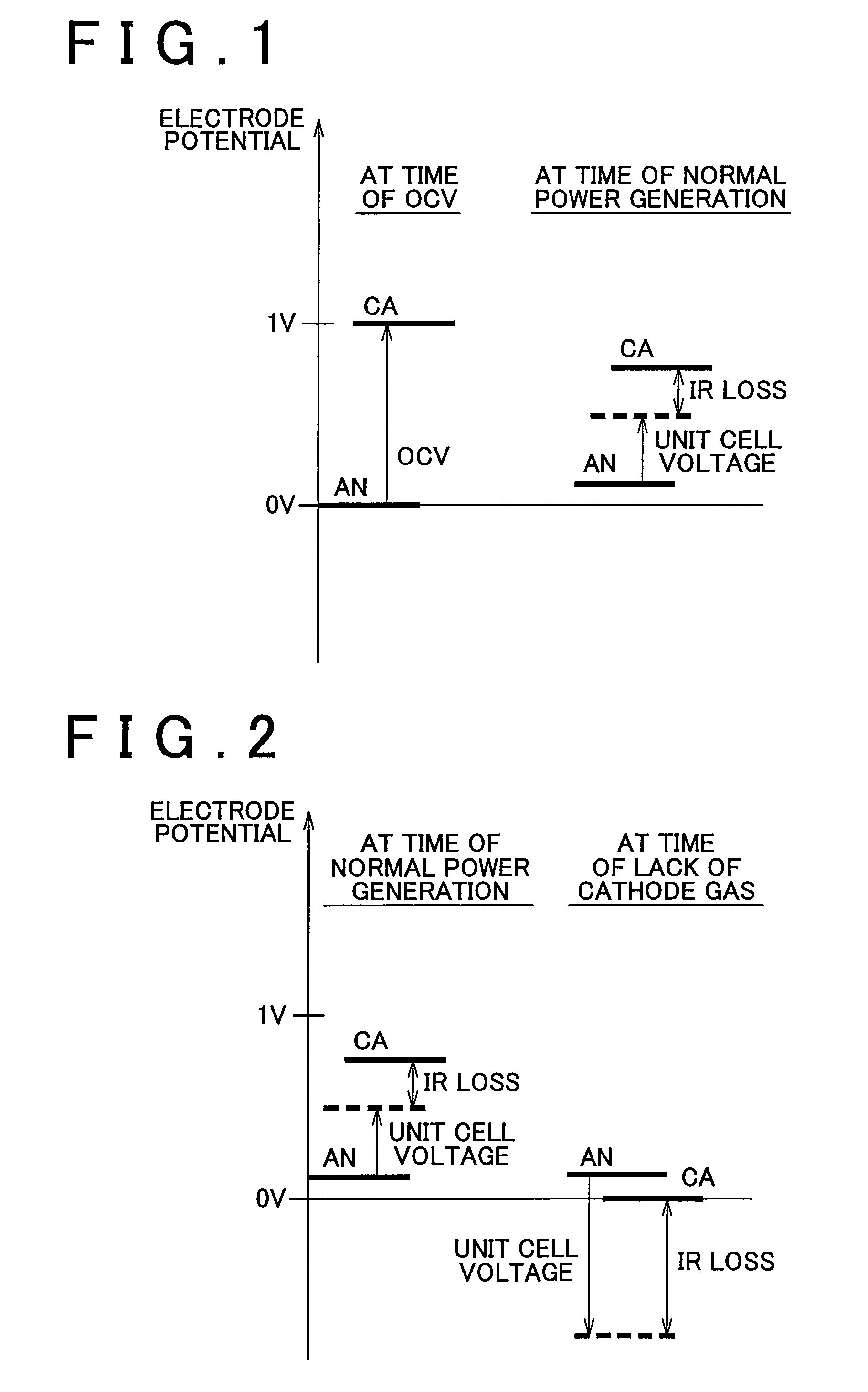
When the oxidant gas is supplied insufficiently, the cathode potential greatly falls from a steady operation potential.
As a result, the cell voltage may sometimes become negative, as in the case of the supply shortage of the fuel gas.
However, unlike the increase in the anode potential due to the supply shortage of the fuel gas, the decrease in the cathode potential due to the supply shortage of the oxidant gas is allowable.
If this is not allowed, the warm-up of the fuel cell cannot be accelerated, so that the startability of the fuel cell at low temperature will decline.
However, only the cell voltage may be measured practically, and thereby each of the anode potential and the cathode potential cannot be practically measured unless a reference electrode is provided.
Therefore, according to the fuel cell system of the related arts, when it is forced to insufficiently supply the oxidant gas for the purpose of warming up the fuel cell system at low-temperature startup, it cannot be determined whether the reverse potential of a unit cell resulted from the increase in the anode potential.

Method used


Image

  • Fuel cell system
  • Fuel cell system
  • Fuel cell system

Examples


embodiment 1

[0048 of the invention will be described with reference to FIGS. 4 to 7.

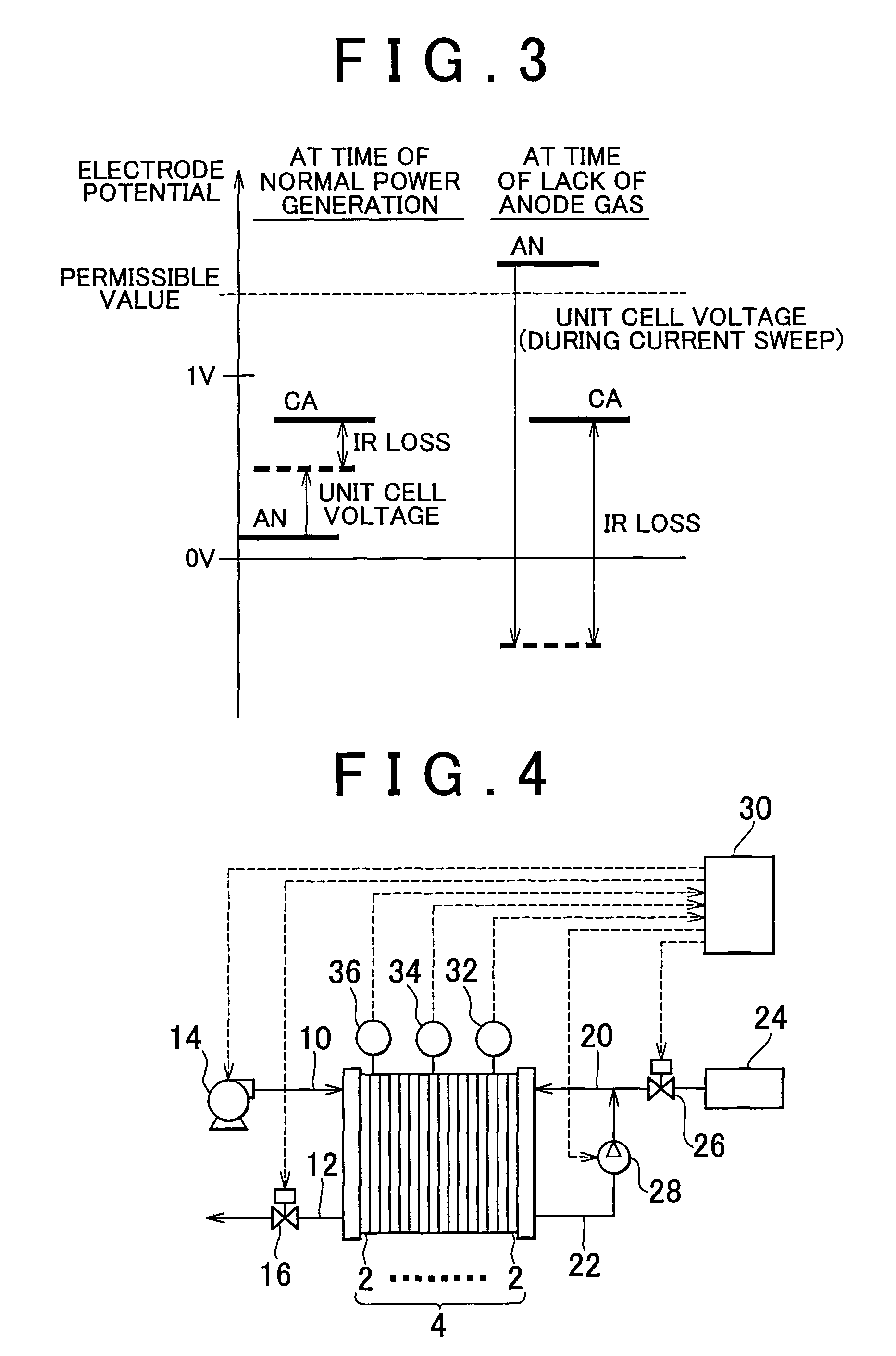
[0049]A fuel cell system according to Embodiment 1 of the invention shown in FIG. 4 will be described below. While FIG. 4 shows an example of the construction of the fuel cell system to which the invention may be applied, the invention is also applicable to fuel cell systems having other constructions. For example, although FIG. 4 shows a so-called “anode gas recirculation system”, the invention is also applicable to a so-called “anode dead end system” in which the anode gas is not recirculated.

[0050]As shown in FIG. 4, the fuel cell system is provided with a fuel cell 4 as an electric power supply source. The fuel cell 4 is constructed of a plurality of unit cells 2 connected in series. Each unit cell 2 generates electric power from a fuel gas containing hydrogen that is supplied to the anode (hereinafter, referred to as “anode gas”) and an oxidant gas containing oxygen that is supplied to the cathode (hereinaf...


PUM

PropertyMeasurementUnit
electric poweraaaaaaaaaa
voltageaaaaaaaaaa
threshold voltageaaaaaaaaaa

Abstract

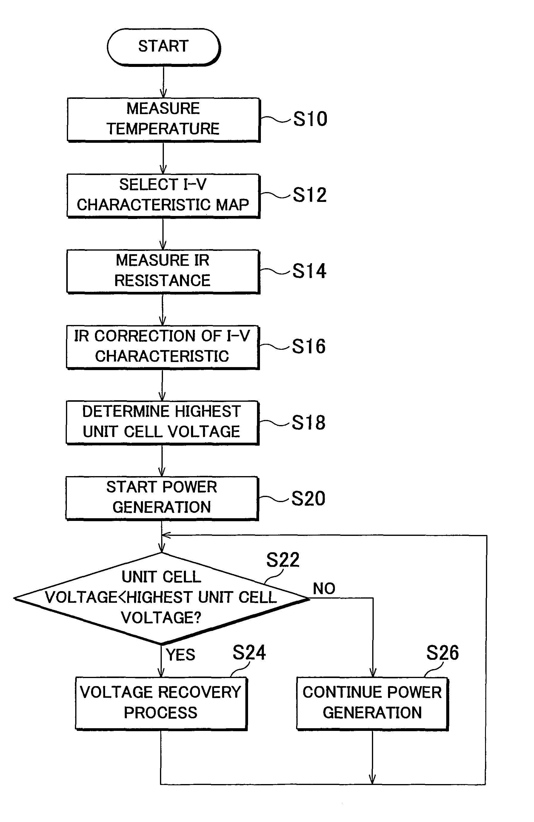
An IR resistance of each of unit cells is measured, and a highest unit cell voltage as a threshold voltage is set based on the IR resistance and load current. The setting of the highest unit cell voltage uses map data that approximates current-voltage characteristics of a unit cell when the fuel gas is insufficiently supplied. In that case, the highest unit cell voltage is determined based on the voltage with respect to the load current obtained from the map data, and the IR loss calculated from the IR resistance and the load current. This highest unit cell voltage is compared with the measured unit cell voltage. If the unit cell voltage is below the highest unit cell voltage, the power generation of the fuel cell is stopped or restrained.

Description

BACKGROUND OF THE INVENTION[0001]1. Field of the Invention[0002]The invention relates to a fuel cell system.[0003]2. Description of the Related Art[0004]Conventionally, the fuel cell is formed with a plurality of unit cells that is connected in series. Each unit cell generates electric power from a fuel gas containing hydrogen that is supplied to the anode, and an oxidant gas containing oxygen that is supplied to the cathode. The amount of supply of a reactant gas (i.e., the fuel gas or the oxidant gas) needed for each unit cell depends on the required generated current (i.e., load current). Therefore, in a fuel cell system, the amount of supply of the reactant gas is controlled in accordance with the load current so as not to become insufficient.[0005]However, for some causes, a reactant gas in one or more unit cells may sometimes become lack of the amount of supply with respect to the needed amount. Examples of such cases include the case where a gas channel in a unit cell is occl...

Claims


Application Information

Patent Timeline
Patent Type & Authority Patents(United States)
IPC IPC(8): H01M8/04
CPCH01M8/04082H01M8/04238H01M8/04253H01M8/04268H01M8/04365H01M8/04552H01M8/04582H01M8/04641H01M8/04753H01M8/04761H01M8/0488H01M8/0494Y02E60/50H01M8/04225H01M8/2457H01M8/0432H01M8/04873H01M8/04932
Inventor KUMEI, HIDEYUKIKATO, MANABU
Owner TOYOTA JIDOSHA KK
Learn More