
Method and apparatus for heat treatment

a heat treatment and material technology, applied in lighting and heating apparatus, combustion types, combustion using lumps and pulverizing fuel, etc., can solve the problems of difficult to keep air from leaking into the combustion zone, requires good pressure control, and is relatively sensitive to air leakage into the combustion zone of oxy-fuel technology, etc., to achieve a high degree of thermal efficiency

Inactive Publication Date: 2005-10-27
LINDE AG
View PDF4 Cites 53 Cited by
  • Summary
  • Abstract
  • Description
  • Claims
  • Application Information

AI Technical Summary

Benefits of technology

[0006] An object of the present invention is to provide a method and an apparatus for heat treatment of metals wherein the drawbacks of prior art apparatuses are eliminated or at least mitigated. A particular object is to provide a method and an apparatus wherein emission of nitrous oxides (NOx) is kept to a minimum while maintaining a high degree of thermal efficiency and providing technology to use oxy-fuel combustion in radiant tubes.

Problems solved by technology

However, oxy-fuel technology is relatively sensitive to air in-leakage into the combustion zone and requires good pressure control in the furnace.
In some processes and furnace types it is very difficult to keep air from leaking into the system
Thus, fuel combustion in a furnace can result in large emissions of nitrous oxides (NOx).
NOx (mainly NO2) emissions have been found to have negative health effects, promote corrosion, and to be an environmental hazard, contributing among other things to eutrophication.
A further problem when using a conventional oxy-fuel burner for heat treatment of metals using radiant tubes is that the high flame temperature of an oxy-fuel burner will damage the tube material, which of course is unacceptable.

Method used


Image

  • Method and apparatus for heat treatment
  • Method and apparatus for heat treatment
  • Method and apparatus for heat treatment

Examples


Embodiment Construction

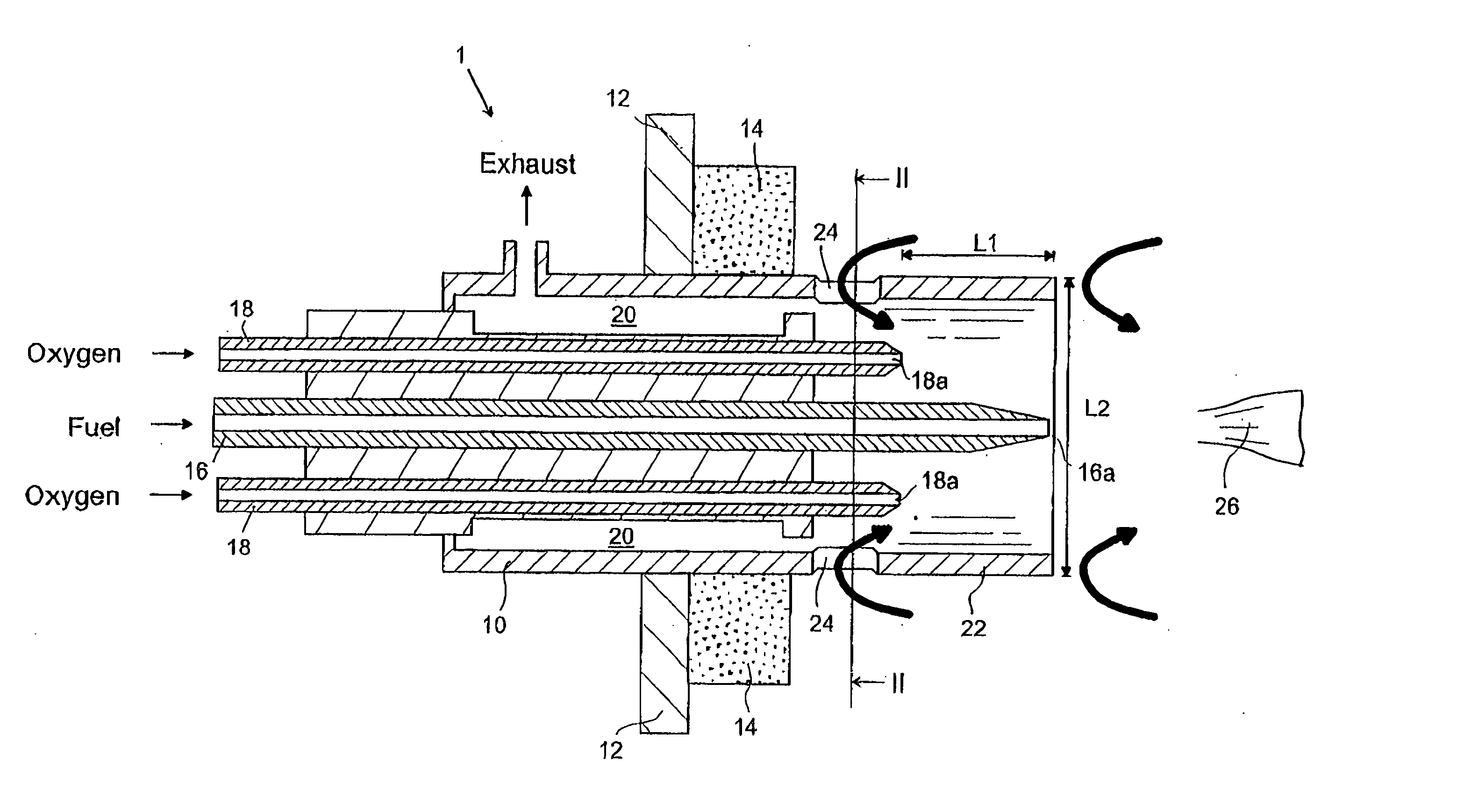
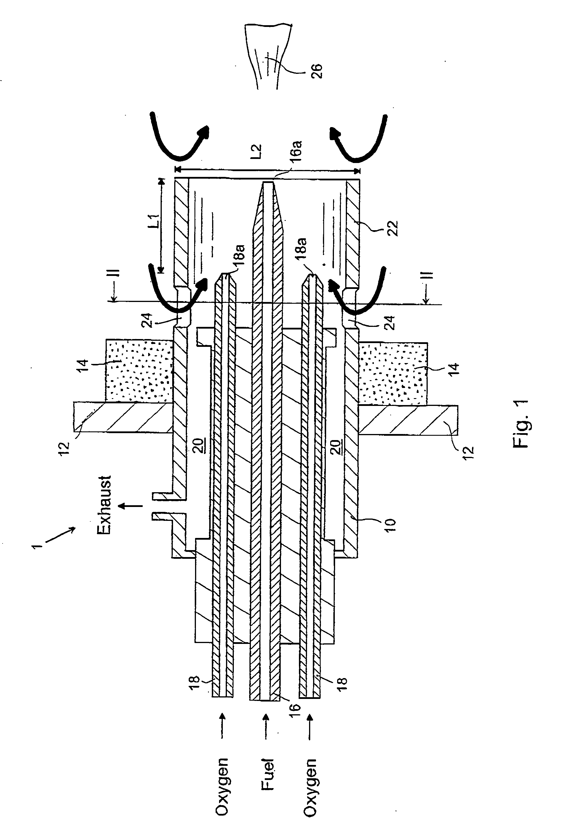
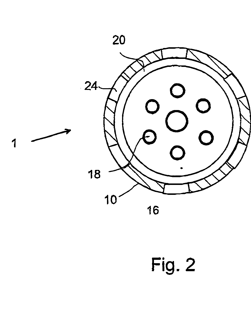
[0019] In the following a detailed description of preferred embodiments of the present invention will be given. In FIG. 1 there is shown a sectional view of a burner arrangement, generally designated 1. The burner arrangement comprises an insert 10 having a generally circular cross-section, see FIG. 2. The insert is arranged to be mounted through a hole in a wall 12 of a furnace (not shown), as is conventional. It is also preferred to arrange a heat insulating material 14 on the hot side of the burner mounting plate 12.

[0020] In the burner body, a fuel supply pipe 16 is centrally provided for supplying fuel, such as natural gas, to a burner reaction zone or flame 26, a portion of which is shown in FIG. 1. The fuel supply pipe is in one end provided with a connector arranged to be connected to a source of fuel (not shown) and in the other end with a fuel nozzle 16a.

[0021] Oxygen is supplied through six equidistant pipes 18 placed at a constant distance from the centre axis of the i...


PUM


Abstract

A method and an apparatus for heat-treatment of materials, preferably metals, are provided. The method comprises the following steps: providing and maintaining a flame by supplying a burner with fuel and gas containing at least 80 percent by volume oxygen; creating an oxygen-hot exhaust mixture by recirculating exhausts from the flame to the gas containing oxygen by means of an ejector effect; mixing the oxygen-exhaust mixture and the fuel; and providing a secondary recirculation by recirculating exhausts from the flame to the oxygen-exhaust-fuel mixture. The method and apparatus allow for extremely low NOx emissions and high efficiency, resulting in an environmentally friendly and at the same time cost effective process.

Description

FIELD OF INVENTION [0001] The present invention relates generally to a method and an apparatus for heat treatment of materials, preferably metals, and more particularly to heat treatment involving low NOx emissions in open flame and radiant tubes as well as a very high thermal efficiency. BACKGROUND [0002] Conventional oxy-fuel technology has successfully been used for many years. It provides great benefits regarding productivity and fuel consumption. Conventional oxy-fuel technology can also be used to achieve considerable reductions in NOx emissions compared to conventional air-fuel burner technology. However, oxy-fuel technology is relatively sensitive to air in-leakage into the combustion zone and requires good pressure control in the furnace. In some processes and furnace types it is very difficult to keep air from leaking into the system [0003] Thus, fuel combustion in a furnace can result in large emissions of nitrous oxides (NOx). NOx (mainly NO2) emissions have been found t...

Claims


Application Information

Patent Timeline
Patent Type & Authority Applications(United States)
IPC IPC(8): F23C9/00F23D14/22F23D14/32
CPCF23C9/006F23C2202/30Y02E20/344F23D14/32F23D14/22F23C1/00F23C15/00
Inventor LUGNET, ANDERSEKMAN, TOMAS
Owner LINDE AG
Learn More