Bone shaped cutting block

a cutting block and bone technology, applied in the field of bone shaped cutting blocks, can solve the problems of increasing surgical time and risk, prolonging patient recovery, etc., and achieve the effect of removing any potential damage to surrounding soft tissu

Active Publication Date: 2005-10-27
HOWMEDICA OSTEONICS CORP
View PDF13 Cites 152 Cited by
  • Summary
  • Abstract
  • Description
  • Claims
  • Application Information

AI Technical Summary

Benefits of technology

[0005] It is therefore one object of the invention to provide a femoral cutting guide for use in minimally invasive surgery (MIS) which has a shape

Problems solved by technology

Such large and complicated incisions increase surgic

Method used


Image

  • Bone shaped cutting block
  • Bone shaped cutting block
  • Bone shaped cutting block

Examples


Embodiment Construction

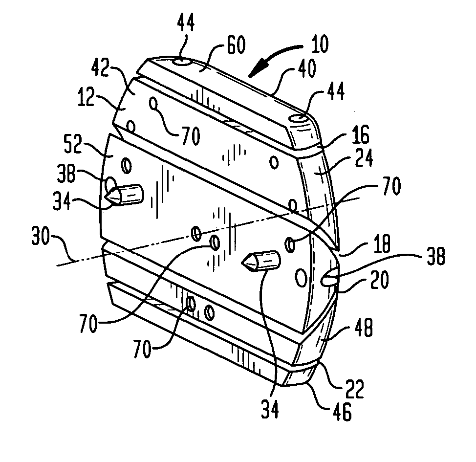
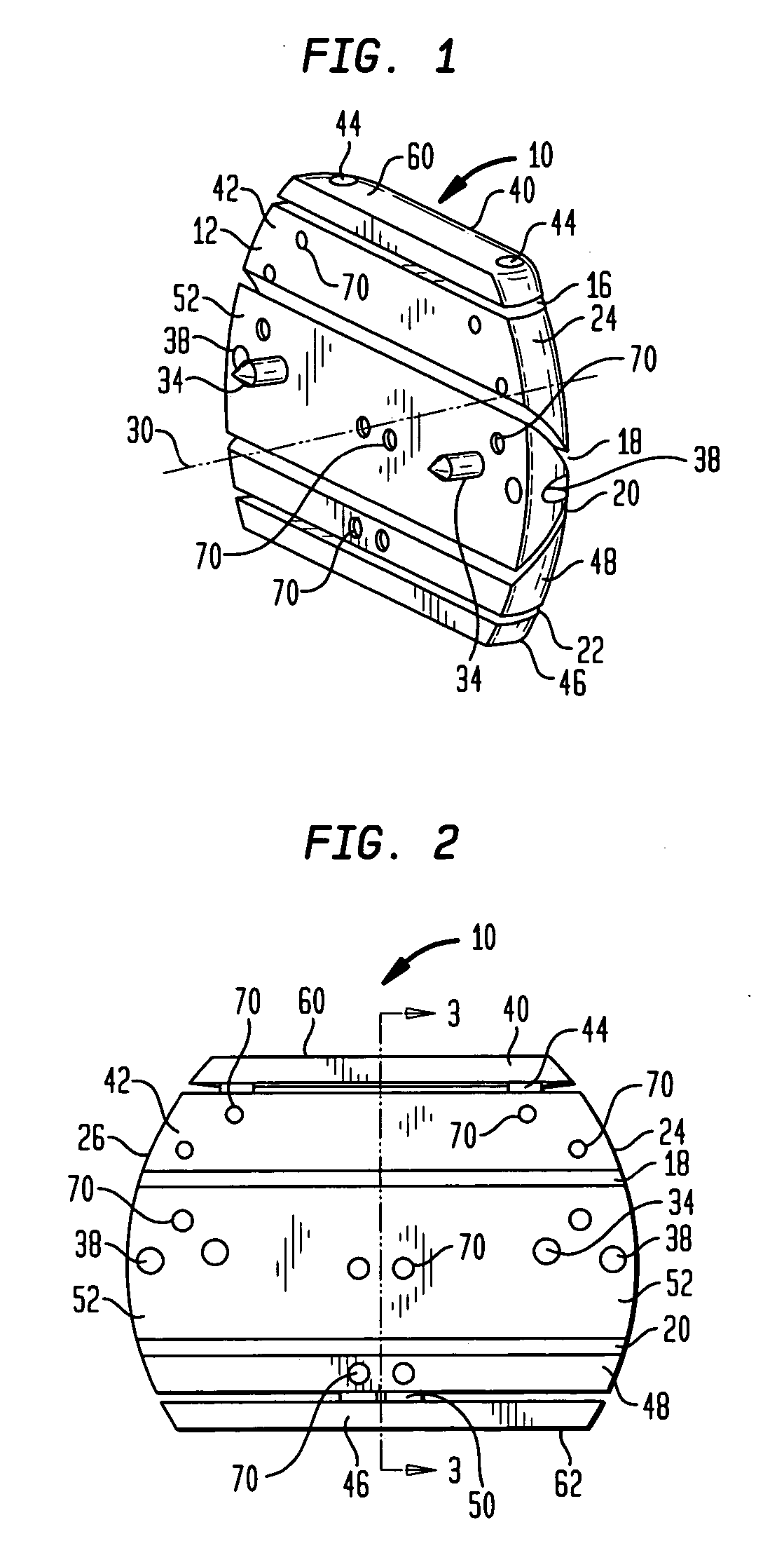
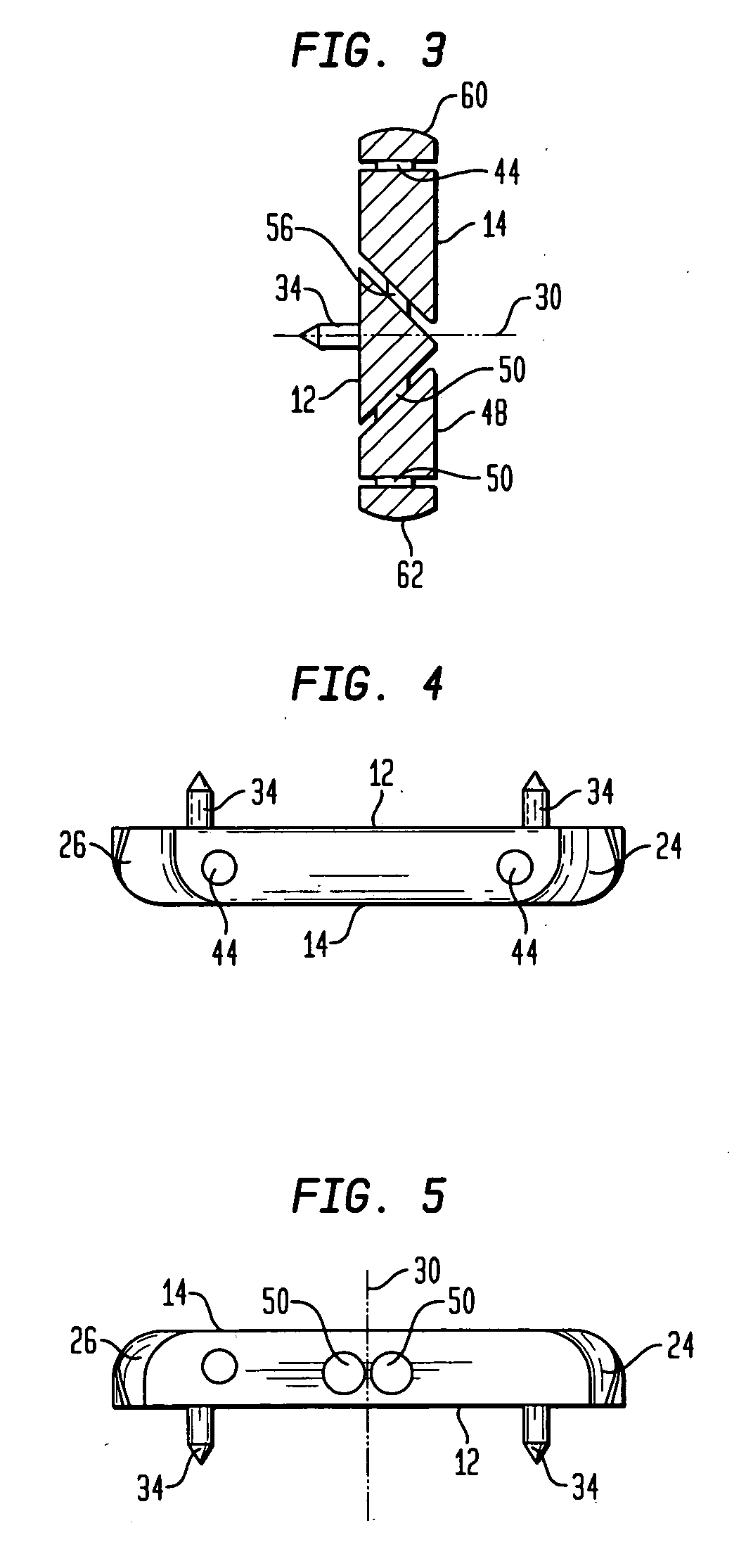
[0024] Referring to the figures, there is shown a cutting block generally denoted as 10 which includes a proximal bone facing surface 12 and an opposite distal facing surface 14. While in the preferred embodiment surface 12 is flat for contacting an already resected distal femur, it is possible to mount the block to a non-resected distal femur and have surface 12 curved to match the shape of the natural condyles. In the preferred embodiment, the block includes four slots 16, 18, 20 and 22, respectively. Slot 16 is adapted to perform an anterior cut, slot 22 is adapted to perform a posterior cut, slot 18 is adapted to an anterior-chamfer cut and slot 20 is adapted to perform a posterior-chamfer cut. These guide slots are preferably used with an oscillating saw blade in a well known manner.

[0025] The cutting block includes perimeter surfaces 24 and 26 which are curved in a plane perpendicular to a central axis 30 perpendicular to the bone facing surface 12 of cutting block 10. Axis 3...


PUM


Abstract

A cutting block for resecting a bone, particularly the distal femur, has a body with a first generally planar bone contacting surface to contact the resected distal surface of the femur. The body has a second surface spaced from the bone contacting surface along an axis perpendicular to said generally planar bone contacting surface. The body has a perimeter surface extending between the first and second surfaces, wherein the perimeter surface is at least partially curved with respect to the axis in both a direction generally perpendicular thereto and generally parallel thereto. The perimeter surface may be polished.

Description

BACKGROUND OF THE INVENTION [0001] The present invention relates generally to the implant of prosthetic joints and pertains, more specifically, to the preparation of the distal femur for the implantation of a femoral knee prosthesis, utilizing a femoral cutting guide to assist in establishing the surfaces necessary for locating and securing the prosthesis in place on the femur. [0002] The implant of a prosthetic knee joint requires that the distal femur be prepared to receive the femoral component of the knee prosthesis by cutting the bone of the femur to establish accurately located surfaces. Upon implantation, the femoral component will rest on these surfaces. As used herein, when referring to bones or other parts of the body, the term “proximal” means closer to the heart and the term “distal” means more distant from the heart. The term “inferior” means toward the feet and the term “superior” means towards the head. The term “anterior” means towards the front part of the body or t...

Claims


Application Information

Patent Timeline
IPC IPC(8): A61B17/00A61B17/15A61F5/00
CPCA61B2017/00238A61B17/155
Inventor AXELSON, STUART L. JR.BARILE, GENNARONEAL, DAVID J.
Owner HOWMEDICA OSTEONICS CORP
Why Eureka
Try Eureka