Power fluctuation suppressing method and power generation facility using same

a technology of power fluctuation and power generation facility, which is applied in the direction of electrochemical generators, machines/engines, secondary cells servicing/maintenance, etc., can solve the problems of power fluctuation that occurs during the time, and achieve the effect of suppressing power fluctuation and suppressing power fluctuation

Inactive Publication Date: 2005-11-03
JFE STEEL CORP
View PDF0 Cites 10 Cited by
  • Summary
  • Abstract
  • Description
  • Claims
  • Application Information

AI Technical Summary

Benefits of technology

[0017] In particular, the present invention provides a method for suppressing power fluctuation of a high-efficiency combined power generation system that uses a byproduct gas generated in a plant. The method includes the steps of adding a high-calorific-value substance having a calorific value higher than that of the byproduct gas so as to increase both the total calorie per unit of time and the calorific value per unit gas quantity up to predetermined targets; and adding a low-calorific-value substance having a calorific value lower than that of the byproduct gas so as to control the caloric value and/or the composition of the power generation fuel, whereby the total calorie and t

Problems solved by technology

Furthermore, in each method described above, the deficiency of power that occurs during the time required for a standby generator to start operation upon shutdown of the high-efficiency combined p

Method used


Image

  • Power fluctuation suppressing method and power generation facility using same
  • Power fluctuation suppressing method and power generation facility using same
  • Power fluctuation suppressing method and power generation facility using same

Examples


example

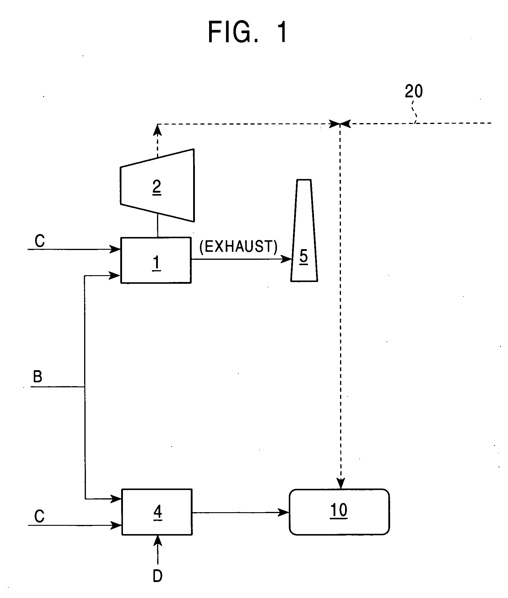
[0089]FIG. 11 illustrates an example of applying the present invention to steelworks. In particular, in the example shown in FIG. 11, a gas-turbine steam combined power generation system (I) including a steam boiler (1) and a gas turbine (3) each driving a power generator (2) was used to perform combined power generation. Two 220 MW power generators were installed. The calorific value and the total calorie of the base fuel gas (byproduct gas) used in power generation were 3,980 kJ / Nm3 and 2,760 GJ / h, respectively. Reference numeral 5 in the drawing denotes a flue.

[0090] A system (II) for accommodating fluctuation of the fuel gas was constituted from two fuel gas mixers (4) and a LNG holder. Reference character C denotes a coke oven gas, B denotes a blast furnace gas, D denotes another byproduct gas, and F denotes exhaust nitrogen gas (or a combustion exhaust gas) from an oxygen plant. The fluctuation of the fuel was accommodated using a liquefied natural gas (LNG) as the heating fu...


PUM


Abstract

The present invention provides a method for suppressing power fluctuation of a high-efficiency combined power generation system that uses a byproduct gas generated in a plant, the method including the steps of adding a high-calorific-value substance having a calorific value higher than that of the byproduct gas so as to increase both the total calorie per unit of time and the calorific value per unit gas quantity up to predetermined targets; and adding a low-calorific-value substance having a calorific value lower than that of the byproduct gas so as to control the caloric value and/or the composition of the power generation fuel, whereby the total calorie and the calorific value are controlled within predetermined ranges. The present invention also provides another method for suppressing power fluctuation of a high-efficiency combined power generation system that uses a byproduct gas generated in a plant, the method including a step of alternately switching charge/discharge modes of at least two storage apparatuses to suppress the fluctuation of the power generated, and a power generating facility for these methods. According to the present invention, not only short-term power fluctuation caused inside the plant but also long-term fluctuation are also suppressed. The excess power, whose fluctuation is suppressed, can be controlled to have a power supply pattern coincident with a power demand pattern so that power can be stably supplied to a site outside the plant.

Description

TECHNICAL FIELD [0001] The present invention relates to a method for generating electric power by using byproduct combustible gasses generated through various industrial activities (hereinafter, “byproduct gas”) as the fuel for high-efficiency combined power generation within industrial plants and to a power generating facility incorporating the method. In particular, the present invention relates to a method for suppressing short-term power fluctuation and long-term power fluctuation that occur when the generated power is sent outside the plant for industrial and consumer use. BACKGROUND ART [0002] Large-scale industries, such as iron making and petroleum refining, generate large amounts of combustible gasses as the byproduct. Conventionally, as shown in FIG. 1, in order to generate electricity from the byproduct gas produced in a plant such as a steelworks, the byproduct gas, such as a blast furnace gas (B) or a coke-oven gas (C), has been introduced into a steam boiler (1) so tha...

Claims


Application Information

Patent Timeline
IPC IPC(8): F02C3/20F02C3/22F02C3/30F02C6/00F02C6/14F02C7/22F02C7/228F02C9/40H01M8/00H01M8/06H01M10/44H02J3/24H02J3/28H02J3/32
CPCF02C3/20F02C3/30F02C3/305F02C6/14F05D2270/061H02J3/24H02J3/28H02J3/32Y02E20/16F02C9/40
Inventor NAKAGAWA, TSUGUHIKO
Owner JFE STEEL CORP
Why Eureka
Try Eureka