
Evacuated glass panel having degassing device

a technology of degassing device and glass panel, which is applied in the direction of instruments, optical elements, mountings, etc., can solve the problems of reducing the mechanical strength of the evacuated glass panel made by this method, the inability to place the degassing device, and the difficulty of removing the degassing device between planar glass sheets, etc., to achieve the effect of eliminating the effluence of stress concentration and micro cracks, increasing the degree of evacuation, and thermal conductivity

Active Publication Date: 2005-11-03
BOE TECH GRP CO LTD
View PDF3 Cites 10 Cited by
  • Summary
  • Abstract
  • Description
  • Claims
  • Application Information

AI Technical Summary

Benefits of technology

[0012] The main object of the present invention is, regarding to the above problem of disposing degassing device during production process of evacuated glass panel, to provide an evacuated glass panel having degassing device, this evacuated glass panel having degassing device can resolve the problem of difficulty in disposing degassing device on one hand, particularly within evacuated glass panel having smaller thickness, and also effectively avoid or greatly reduce the inner stress and micro crack at place of degassing device on the other hand, there by increasing the mechanic strength of evacuated glass panel, making it not easy to break in use and increasing the ratio of qualitative evacuated glass panel during production.
[0013] A further object of the present invention is, regarding to above shortage in operation complexity and easy air leak, to provide an evacuated glass panel having degassing device, said evacuated glass panel has an even sealing surface of the air discharge hole, effectively overcoming the problem of traditional protruded sealing surface easy to be damaged and resulted in air leak.
[0022] In the technical schemes of this invention, the low melting point glass powder is applied in groove, in which degassing device fixed, after sintering it becomes a low melting point glass powder layer. This scheme can insure under the premise of further increasing degree of evacuation, to eliminate the effluence of stress concentration and micro crack on the strength of evacuated glass panel by of low melting point glass powder layer.
[0023] Because the degassing device is sintered to groove of planar glass, the low melting point glass powder has thermal conductivity far lower than that of glass, the instantaneous heating degassing device not exert a very large influence, there by decreasing the energy consumption and increasing operation effect, and the ratio of qualitatively finished product is greatly improved.
[0024] This is not only one, in the technical scheme of present invention because the groove is simultaneously opened on inner surface of top and bottom planar glass sheets, particularly the air discharge hole can be used for placing degassing device, this makes the deepness of groove rather shallow, the mechanic strength of evacuated glass panel specially evacuated glass panel specially evacuated glass panel specially evacuated glass panel of thin type greatly increased.
[0025] Moreover, due to the employing even sealing piece for sealing air discharge hole, the danger of air leak in assembly and use is reduced.

Problems solved by technology

However, during manufacturing evacuated glass panel manufacturing evacuated glass panel having smaller thickness, the disposing degassing device between planar glass sheets became very difficult.
Because the space between planar glass sheets is very small, and the size of degassing device is always larger than the space between planar glass sheets of evacuated glass panel, such the degassing device can not be placed in.
The evacuated glass panel made by this method has greatly reduced mechanical strength, this is because that at the time of groove forming, around groove the stress is excessively concentrated, at same time around groove micro crack is easily occurred, and when the degassing device is heated to high temperature, the micro crack may further spread.
The micro crack and concentration of stress may lead to fracture of the evacuated glass panel during manufacture process or practical use therefore, the concentration of stress and occurrence of micro crack greatly decrease the mechanical strength of evacuated glass panel.
Because the hole sealing place is protruded from planar glass sheet, a further technologic treatment is necessary, if a mechanic cap or sealing layer protect is added, the structure of sealing air discharge hole is rather complex, many operations is necessary; in some case the solder glass and sealing piece is used to sealing air discharge hole, however, in order to insure absence of air leak in air discharge hole, the solder glass and sealing piece is protruded from planar glass sheet after it is melted.
Due to the sealing place of air discharge hole is uneven after its sealing, said sealing place is easy to be damaged and resulted in air leak during assembling and transporting evacuated glass panel, there by losing the thermo and sound-insulating effect of evacuated glass panel.

Method used


Image

  • Evacuated glass panel having degassing device
  • Evacuated glass panel having degassing device

Examples


example 1

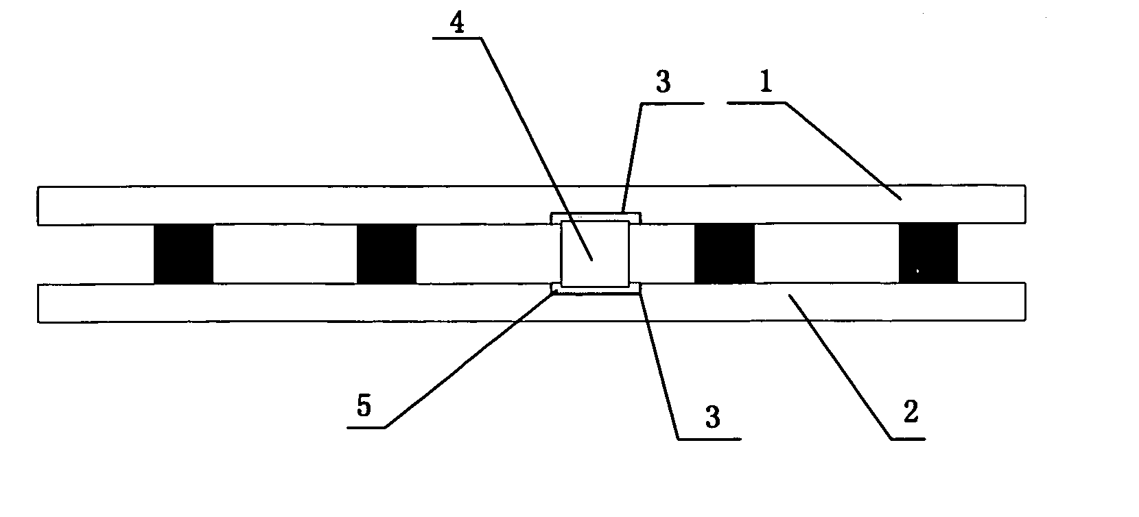
[0029] As shown in FIG. 1, on the inner surface of top planar glass sheet 1 and bottom planar glass sheet 2 two grooves 3 are simultaneously opened, in groove 3 the degassing device 3 is placed, there by increasing the degree of evacuation and radiation resistance. The tow simultaneously opened grooves avoid the difficulty due to small space of evacuated chamber. The low melting point glass powder is firstly applied between groove 3 and degassing device, then the degassing device is placed, after sintering the low melting point glass powder is solidified forming a low melting point glass powder layer 5. The formed low melting point glass powder layer 5 fixed the degassing device 4 in groove 3.

[0030] After the operation of evacuation of evacuated glass panel vaporization activated by high frequency is performed in order to absorb residual gas and increase degree of evacuation, making this embodiment have thermo and sound insulating effect.

[0031] Moreover, because the low melting po...

example 2

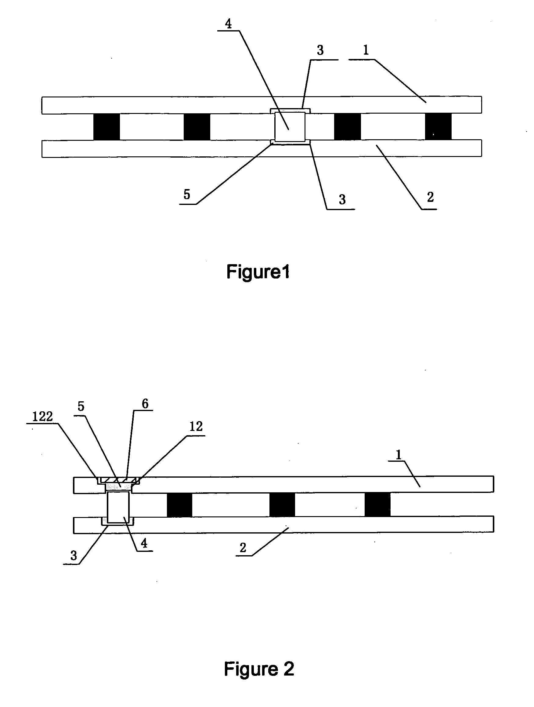
[0032] As shown in FIG. 2, on the surface of top planar glass sheet, a air discharge hole 12 for evacuation is opened, around the periphery of said air discharge hole 12 the outer surface of glass sheet a concave portion 122 is opened, said concave portion 122 can receive a sealing piece 6; said sealing piece 6 through the low melting point glass powder layer 5 is fixed in said concave portion 122, and close said air discharge hole 12 after evacuation of evacuated glass panel.

[0033] Said sealing piece has a thickness corresponding to the total thickness of the low melting point glass powder layer 5, and equal to the deepness of the concave portion 122, there by making the place of sealing air discharge hole 12 sufficiently even, thus the problem of air leak can be avoid.

[0034] On the inner surface of bottom glass sheet 2 a groove 3 is opened for placing the degassing device 4, position of said groove 3 is the same as that of said air discharge hole 12 on glass sheet 1.

[0035] Duri...


PUM


Abstract

An evacuated glass panel having degassing device, which includes at least tow planar glass sheets having any shape and support means posed therebetween, edge frame component sealed around periphery of the planar glass sheet, and degassing device disposed in the evacuated space of evacuated glass panel; between said degassing device and said groove a low melting point glass powder layer is placed and said low melting point glass powder layer is fixed in said groove.

Description

TECHNICAL FIELD [0001] The present invention relates to an evacuated glass panel having degassing device, particularly, an evacuated glass panel having degassing device disposed in evacuated chamber of thinner evacuated glass panel, the present invention concerns the technical field of glass manufacturing. BACKGROUND OF THE ART [0002] The evacuated glass panel is a high thermo and sound insulating glass panel made by evacuation of the space between planar glass sheets, periphery of which is sealed. [0003] The evacuated glass penal is forge rapidly ahead through nearly a hundred years investigation and development. Both the theoretical study and proved that evacuated glass panel is an ideal thermo and sound insulating material and it can be used in door and window of building and thermo-insulating cabinet, refrigerator or freezing cabinet in order to a chive higher thermo and sound insulating effect, must provide higher degree of evacuation. [0004] In order to increase the degree of ...

Claims


Application Information

Patent Timeline
IPC IPC(8): E06B3/663E06B3/677
CPCE06B3/6612E06B3/66304Y02B80/24E06B3/6775E06B3/677Y02B80/22Y02A30/249
Inventor WU, JUSHENGLI, HONGYAN
Owner BOE TECH GRP CO LTD
Learn More