
Electronic toy and teaching aid safety devices

Active Publication Date: 2005-11-03
ELENCO ELECTRONICS LLC
View PDF10 Cites 44 Cited by
  • Summary
  • Abstract
  • Description
  • Claims
  • Application Information

AI Technical Summary

Benefits of technology

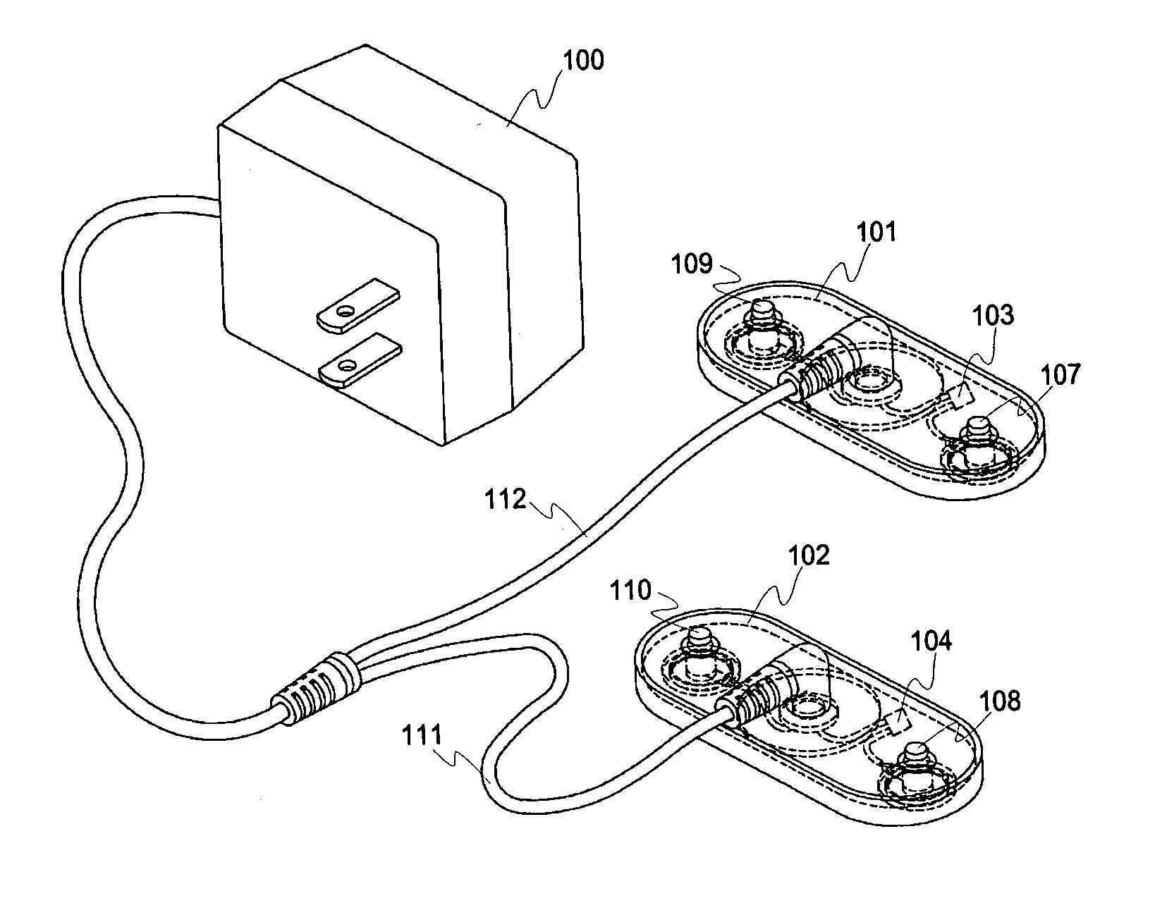
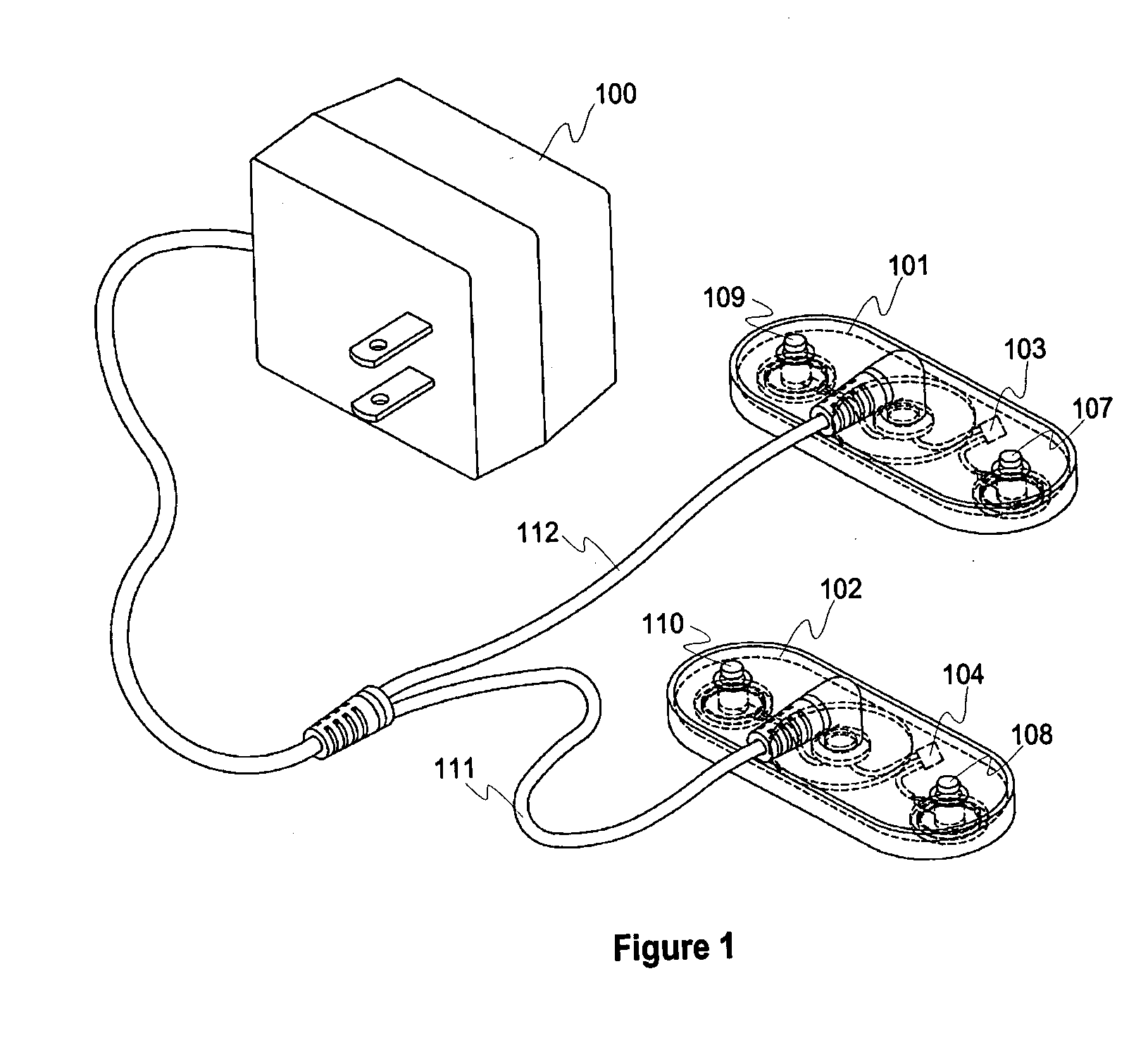
[0008] This PTC fuse will rise in resistance value and limit the amount of current flowing whenever it is raised in temperature. By placing it in series with electronic components, it will limit both AC and DC currents to a safe level if the parts are used incorrectly. As current increases the temperature of the PTC also increases. This raises the resistance of the PTC which lowers the voltage and prevents damage to the electronic components. As soon as the electrical current level is restored to a safe level, the temperature of the PTC will drop allowing circuits to receive the proper voltage. Placing the PTC inside the battery holder or inside the quick connect circuit AC / DC power plug, prevents the user from touching it when it is at an elevated temperature. The use of non-polarized capacitors will help take care of incorrect DC connection of capacitors but will not cure the problem of extremely high AC currents through capacitors that can also cause heating and explosion. By placing PTC resetable fuses, that cannot be removed by the child or student, in series with sensitive electronic components of all these problems can be eliminated. Adding the PTC resetable fuse in series with any “off the shelf” component will likewise prevent excessive current from flowing. Any module that accepts non-polarized capacitors or “off the shelf” components should have this type of protection.

Problems solved by technology

Whenever new circuits are constructed the potential for damage to the parts will occur and safety problems will arise.
This device can be inside the module and not available to the child or student for maximum amount of protection.
The use of non-polarized capacitors will help take care of incorrect DC connection of capacitors but will not cure the problem of extremely high AC currents through capacitors that can also cause heating and explosion.

Method used


Image

  • Electronic toy and teaching aid safety devices
  • Electronic toy and teaching aid safety devices
  • Electronic toy and teaching aid safety devices

Examples


Embodiment Construction

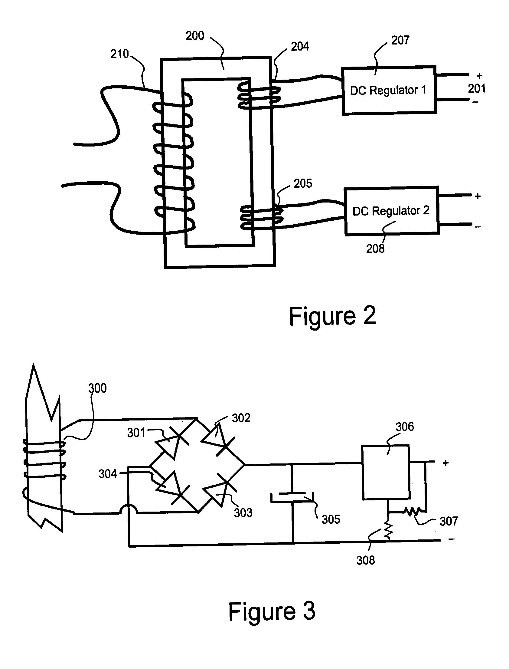
[0016] The present inventions consist of an improved battery holder module 600, Positive Temperature Coefficient Automatically Resetable Fuses 103, 104, 404 and 605, a specially designed power source 100 with unique stackable output plugs 101 and 102, a quick connect module 400 for electronic components, a clear see through plastic base 500 with mechanical compatible connectors for quick connect circuit interfacing some of which are shown as components 510-516, 600. The battery holder module 600 is designed to be used as a direct replacement for existing quick connect circuit type battery holder modules. The clear plastic base 500 serves as a support to mount the quick connect circuit modules.

[0017] The quick connect circuit systems that are presently being sold use battery holders that can be placed in series to stack the voltages. The addition of the Positive Temperature Coefficient Automatically Resetable Fuse 605 prevents shorts from producing heat that can damage the battery h...


PUM


Abstract

A battery holder containing positive temperature coefficient (PTC) resetable fuse to electronically limit the maximum current that can be drawn from circuits built using reusable electronic component housings. A power supply with similar housing to reusable battery holders, also designed to limit maximum current and perform electrically equivalent to two or more battery holders. A reusable electronic housing with means for attaching any two leaded electronic component for insertion into quick connect assembly system. This housing also contains a positive temperature coefficient (PTC) resetable fuse to electroniclly limit the maximum current that can be sent through the attached two leaded component.

Description

FIELD OF THE INVENTION [0001] This invention relates generally to devices used with circuits that easily and quickly connect together and specifically to circuits constructed by children or students. It insures that the circuit will be safe and is designed to prevent damage to components or any object or person in close proximity to these components. BACKGROUND OF THE INVENTION [0002] There are toys and teaching aids that use a mechanical connector to quickly assemble electronic circuits. Sooner or later these components are connected to a power source such as a battery. If the circuit allows too much current to flow, certain devices may become extremely hot and even explode. [0003] Fuses may be connected in series with the power source that will open when excessive current flows. Since most inexpensive fuses must be replaced, this process is inconvenient and allows the child or student the option of using a conductor that eliminates the protection device. Mechanically resetable fus...

Claims


Application Information

Patent Timeline
IPC IPC(8): H01R13/627H02H3/08
CPCH01R13/627
Inventor SEYMOUR, ARTHUR F.
Owner ELENCO ELECTRONICS LLC
Learn More