All-optical signal regeneration

Inactive Publication Date: 2005-11-03
CORNING INC
View PDF10 Cites 9 Cited by
  • Summary
  • Abstract
  • Description
  • Claims
  • Application Information

AI Technical Summary

Benefits of technology

[0008] The present invention provides a technique utilizing this principle but

Problems solved by technology

Optical pulse signals are liable to degradation as a result of undesirable reflections, chromatic and polarization dispersion, self-phase and cross-phase modulation and other causes, and if bit errors are to be avoided on long routes, need not only to be amplified but also to be regenerated either to restore the original pulse format or to change to another satisfactory format.
A difficulty with this concept is that if, as will normally be th

Method used


Image

  • All-optical signal regeneration
  • All-optical signal regeneration
  • All-optical signal regeneration

Examples


Embodiment Construction

[0018] Reference will now be made in detail to the present preferred embodiments of the invention, examples of which are illustrated in the accompanying drawings. Whenever possible, the same reference numerals will be used throughout the drawings to refer to the same or like parts.

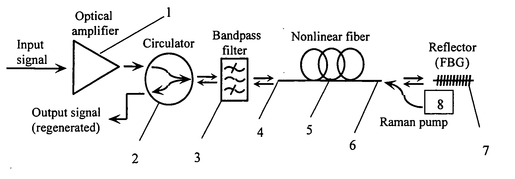
[0019]FIG. 1 represents a simple form of the regenerator in accordance with the invention, and thus illustrates the key steps of the method of the invention. An optical input signal in a return-to-zero pulse format at a first wavelength which will be designated λ1 is first amplified by an optical amplifier 1 (erbium-doped fiber amplifiers, Raman amplifiers and semiconductor optical amplifiers are all suitable) and then passed via a circulator 2 and a bandpass filter 3 tuned to the wavelength λ1 (whose respective functions will be detailed shortly) to enter the first or left-hand end 4 of a length of highly nonlinear optical fiber 5. Due to self-phase modulation in the fiber, it emerges from the second or ...


PUM


Abstract

An all-optical method of regenerating an optical return-to-zero format pulse signal of a first wavelength starts by introducing the input signal into a first end of a non-linear optical fiber to obtain a modified signal comprising pulses broadened in the wavelength domain. When this modified signal emerges from the second end of said non-linear optical fiber, a bandwidth slice is selected that is centered on a second wavelength so spaced from the first wavelength that its intensity is substantially unresponsive to weak pulses in the signal and relatively insensitive to intensity for other pulses. This slice is returned to the same non-linear optical fiber at its second end so that a further modified signal comprising pulses broadened in the wavelength domain will emerge from its first end. From this further modified signal a bandwidth slice centered on the first wavelength is selected as regenerated output. Regenerators operating in this way are also disclosed.

Description

BACKGROUND OF THE INVENTION [0001] 1. Field of the Invention [0002] The present invention relates generally to optical communications technology, and particularly to the regeneration of optical signals in return-to-zero pulse formats. [0003] 2. Technical Background [0004] Optical pulse signals are liable to degradation as a result of undesirable reflections, chromatic and polarization dispersion, self-phase and cross-phase modulation and other causes, and if bit errors are to be avoided on long routes, need not only to be amplified but also to be regenerated either to restore the original pulse format or to change to another satisfactory format. This can be done by detecting the pulses, reshaping the resulting electrical signal, and modulating it onto a new optical carrier, but it is clearly preferable if practicable to regenerate in the “optical layer”, that is without conversion to an electrical signal. [0005] It is known that if an optical pulse passes through a length of non-lin...

Claims


Application Information

Patent Timeline
IPC IPC(8): H04B10/02H04B10/17H04J14/02H04J14/08
CPCH04B10/299H04J14/0241H04J14/0227
Inventor EVANS, ALAN F.KUKSENKOV, DMITRI V.
Owner CORNING INC
Why Eureka
Try Eureka