Device for fixing a vacuum pump

a vacuum pump and device technology, applied in the field of vacuum pumps, can solve the problems of violent multi-directional shear force, unbalanced running at full speed of rotation, insurmountable difficulty, etc., and achieve the effect of relieving the screw shank and improving mechanical strength properties

Inactive Publication Date: 2005-11-03
ALCATEL LUCENT SAS
View PDF25 Cites 13 Cited by
  • Summary
  • Abstract
  • Description
  • Claims
  • Application Information

AI Technical Summary

Benefits of technology

[0025] A further improvement in the mechanical strength properties is also obtained by providing an elastomer type damper material which is inserted in the space between the screw shank and the corr...

Problems solved by technology

However, it has been found that an insurmountable difficulty can arise in the event of the rotor of the pump being accidentally destroyed while rotating at full speed.
Under such circumstances, the rotor running at its full speed of rotation becomes unbalanced and can strike the wall of the pump body violently, thereby imparting a transverse or radial displacement thereto, and can rub strongly against the wall of the pump body, thereby imparting a coaxial rotary torque thereto.
This results in violent multidirectional shear forces being applied t...

Method used


Image

  • Device for fixing a vacuum pump
  • Device for fixing a vacuum pump
  • Device for fixing a vacuum pump

Examples


Embodiment Construction

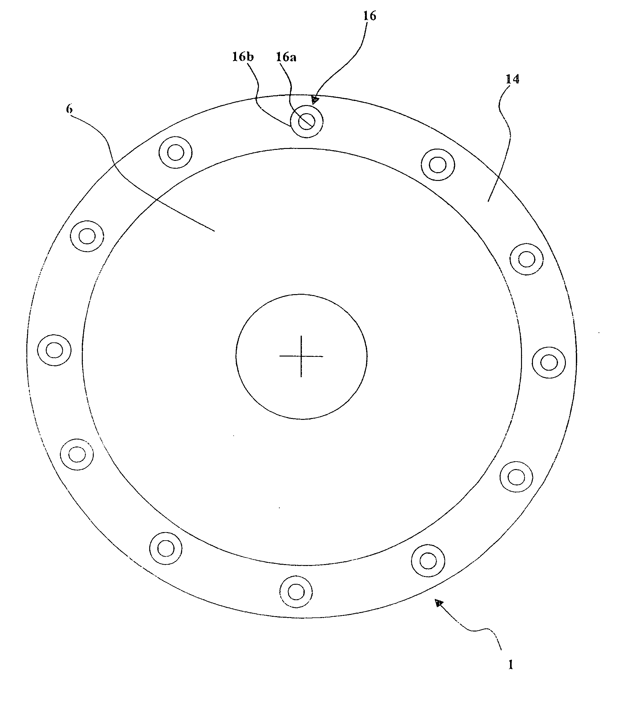
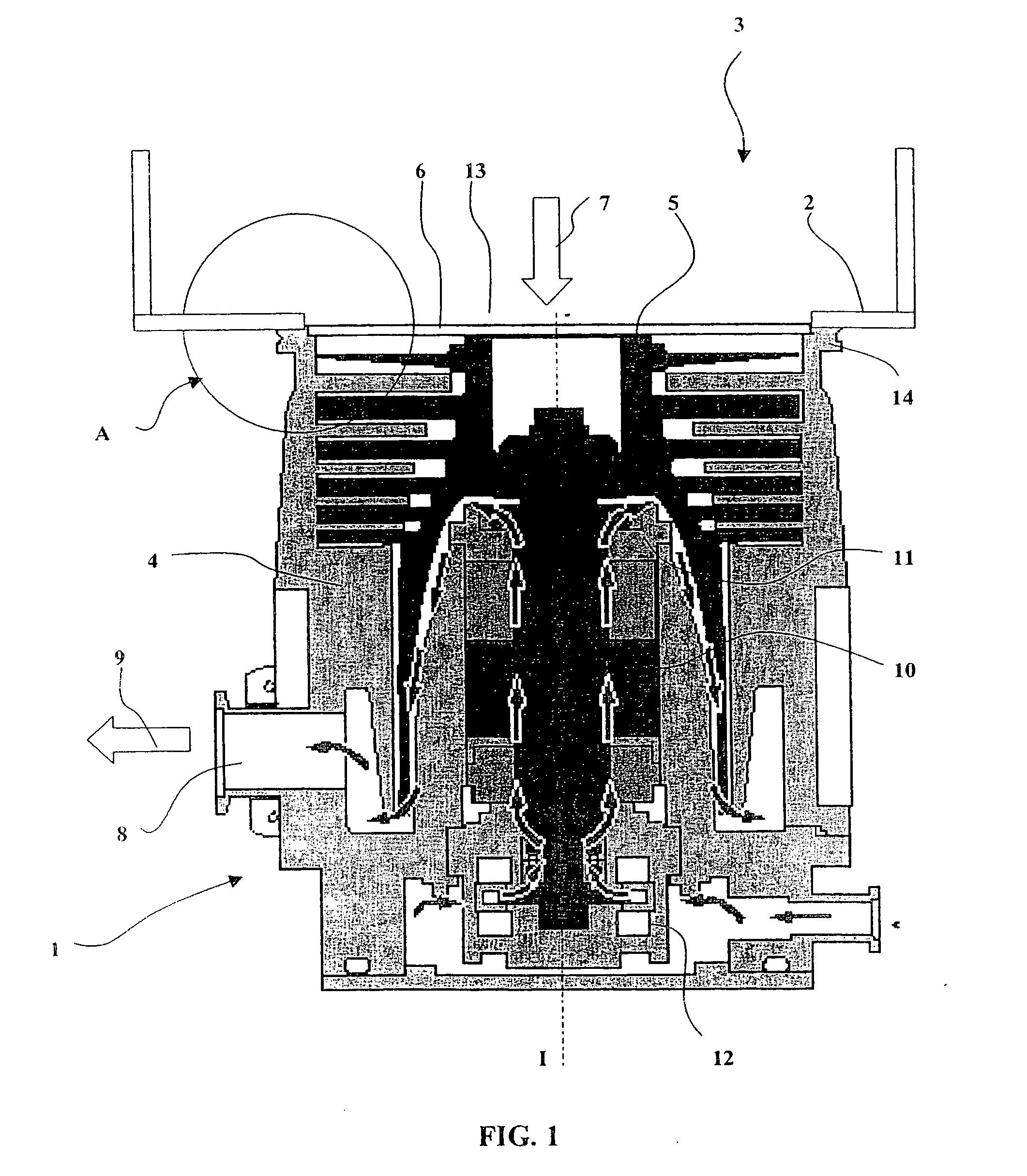
[0033] Reference is made initially to FIG. 1 showing the structure of a vacuum pump 1 of the turbomolecular type, secured to the wall 2 of a stationary structure 3 such as vacuum enclosure.

[0034] The turbomolecular vacuum pump 1 comprises a pump body 4 in which a rotor 5 rotates at high speed about an axis of rotation I. The pump body 4 has a suction orifice 6 on the axis, through which the pumped gas 7 penetrates, and an exhaust orifice 8 through which the outlet gas 9 is exhausted. The rotor 5 is rotated in the pump body 4 by an internal motor 10, and it is guided laterally by magnetic or mechanical bearings 11 and 12.

[0035] The wall 2 of the vacuum enclosure 3 has an outlet orifice 13 corresponding to the suction orifice 6 of the vacuum pump 1, and generally constitutes a closed enclosure that is isolated from the outside and in which the vacuum pump 1 can establish a controlled vacuum.

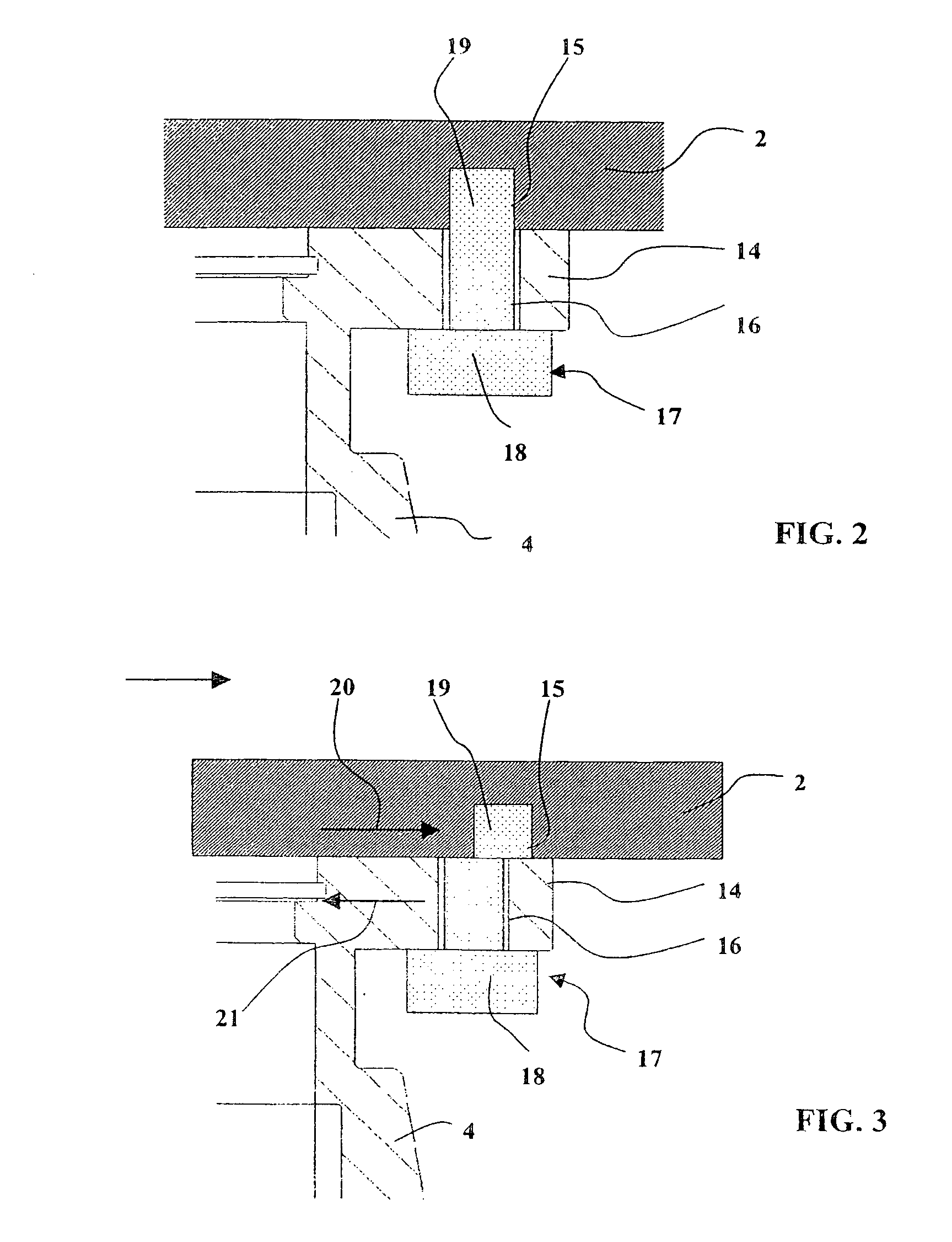
[0036] A coaxial annular flange 14 is provided on the vacuum pump body 4 around the suction ...


PUM


Abstract

The fastener system of the invention comprises a coaxial annular flange (14) having through holes (16) provided therein, each serving to pass a screw (17) for screwing into an associated tapped hole (16) in the wall (2) of a stationary structure. Each through hole (16) comprises a circularly cylindrical distal segment (16a) followed by an enlarged proximal segment (16b) adjacent to the wall (2) of the stationary structure, and allowing the shank (19) of the screw to bend and enabling a corresponding lateral offset (D). This prevents the screw (17) rupturing under high shear forces due to accidental destruction of a vacuum pump rotor while rotating at full speed.

Description

TECHNICAL FIELD OF THE INVENTION [0001] The present invention relates to vacuum pumps having a high speed of rotation that are secured and connected to a stationary structure such as a vacuum enclosure or a pipe for generating a high vacuum. [0002] In the electronic or micromechanical components industry, methods of machining or plasma treatment are used that are performed in an enclosure where it is necessary to maintain a controlled vacuum atmosphere. [0003] Generating a vacuum requires pumps to be used that are capable of generating a high vacuum quickly and of maintaining it, which pumps should be adapted to the method of machining or treatment. In general, the pumps are used are of the turbomolecular type, comprising a pump body in which a rotor is driven to rotate at high speed, e.g. at more than 30,000 revolutions per minute (rpm). [0004] With such a high speed of rotation, the rotor acquires a very high level of kinetic energy. [0005] The pump body has a suction orifice on i...

Claims


Application Information

Patent Timeline
IPC IPC(8): F04D19/04F04D27/02F04D29/60F04D29/64
CPCF04D19/04F04D29/601F04D27/008Y10T403/3981Y10T403/75Y10T403/64Y10T403/642Y10T403/4691Y10T403/645F16B2200/50F16B2200/403F16B2200/503F16B2200/506
Inventor MATHES, RAINERDAUVILLIER, OLIVIERDULAC, ERICBOUILLE, ANDRESAVRY, CHRISTIAN
Owner ALCATEL LUCENT SAS
Why Eureka
Try Eureka