Deep hole drill

Inactive Publication Date: 2005-11-03
GUEHRING JOERG
View PDF13 Cites 10 Cited by
  • Summary
  • Abstract
  • Description
  • Claims
  • Application Information

AI Technical Summary

Benefits of technology

[0031] In another preferred aspect of the present invention, the drill shank consists of a formed tube of heat-treatable steel. The straight-running machined groove can be impre

Problems solved by technology

Thus, a plurality of time-consuming work processes are required to adjust the position of the cutting edge to the desired nominal diameter or to equip the cutter carrier with the c

Method used


Image

  • Deep hole drill
  • Deep hole drill
  • Deep hole drill

Examples


Embodiment Construction

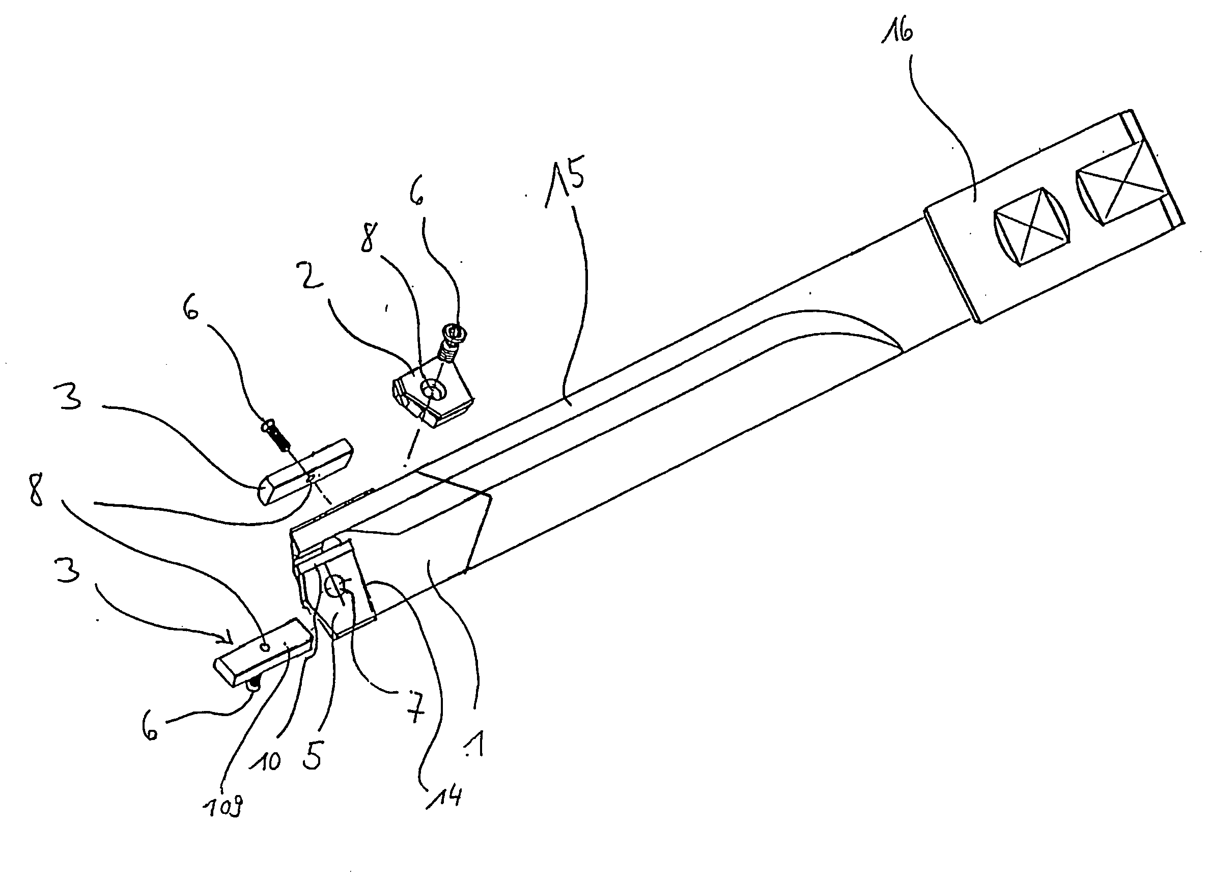
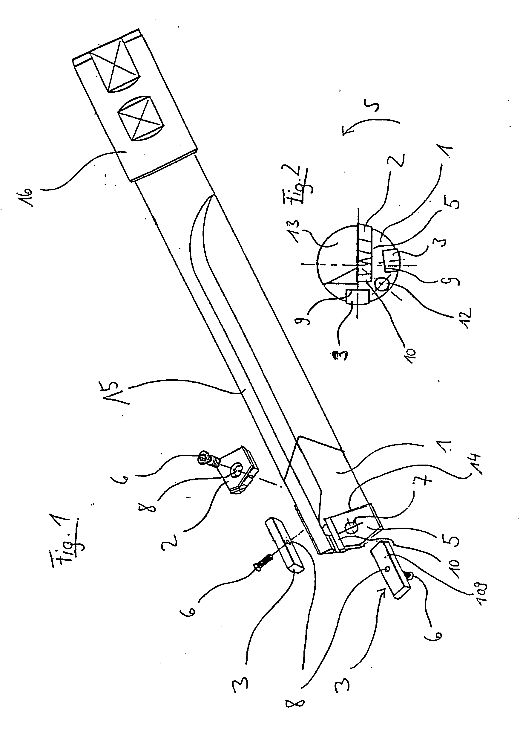
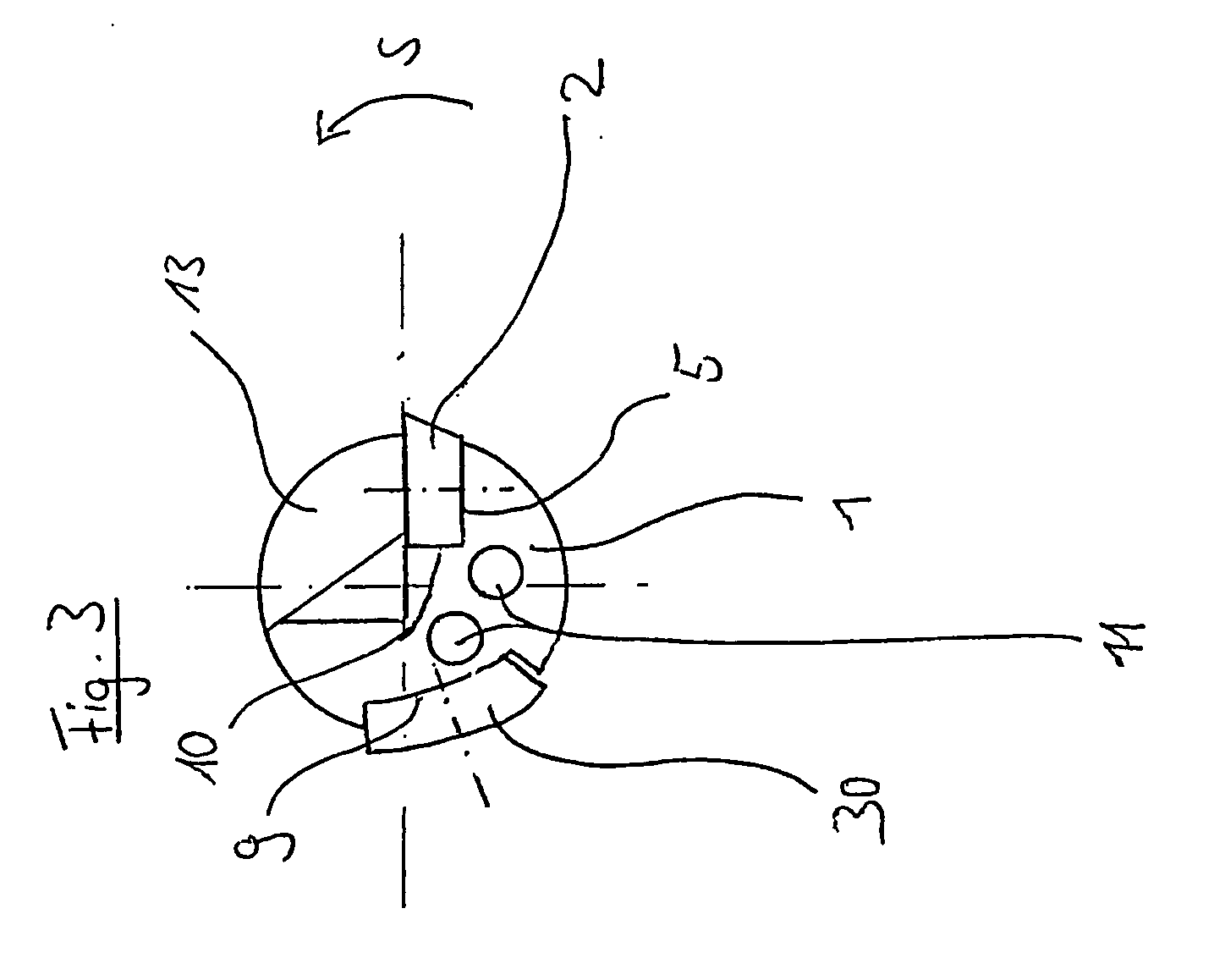
[0041] Reference is first made to FIGS. 1 and 2 which show a single-lipped embodiment of the deep hole drill according to the invention. The reference number 1 designates a drill head which is soldered onto a drill shank 15 which in turn is soldered into a clamping sleeve 16. The machined groove is substantially v-shaped where the angle spanned by the machined and unmachined surface is approximately 90°.

[0042] At its tip, on the machined surface of the machined groove 13 the drill head has a recess which with its rear surface 5 and the two side surfaces 10, 14 forms a seat for a replaceable cutting plate 2. A central threaded hole 7 is drilled into the rear surface 5 which receives a screw 6 guided through a through hole in the replaceable cutting plate 2.

[0043] Furthermore, at the axial height of the replaceable cutting plate seat two recesses for guide strips 3 are provided over the circumference of the drill, which abut against a stop surface 9 with their radially-pointing plan...


PUM

PropertyMeasurementUnit
Angleaaaaaaaaaa
Diameteraaaaaaaaaa
Distanceaaaaaaaaaa

Abstract

A deep hole drill comprising a cutter carrier, a replaceable cutting insert and at least one replaceable guide strip. The cutter carrier is embodied in such a way that it can be used for a predetermined nominal diameter range. In order to adjust the deep hole drill to the various desired nominal diameters in a quicker and more precise manner, a separate kit consisting of a cutting insert and at least one guide strip is associated with each nominal diameter. Fixed stops are provided on the cutter carrier for said kit.

Description

[0001] This application is a continuation of International Application PCT / DE2003 / 004274, filed Dec. 18, 2003, the entirety of which is incorporated herein by reference.CROSS-REFERENCE TO RELATED APPLICATIONS [0002] This application claims the benefit of German Patent Application No. 202 19 754.9, filed Dec. 19, 2002, the entirety of which is incorporated herein by reference. BACKGROUND OF THE INVENTION [0003] The invention relates to a deep hole drill comprising a cutter carrier, a replaceable cutting insert and at least one replaceable guide strip wherein the cutter carrier can be used for a predetermined nominal diameter range, and a range for equipping a cutter carrier for such a deep hole drill wherein a new type of equipping method can be implemented with this range. [0004] In single-lip deep hole drills the swarf is removed by means of a supplied lubricant via the relatively large, straight-grooved machined groove as a result of the single-lip geometry. The actual cutting pro...

Claims


Application Information

Patent Timeline
IPC IPC(8): B23B51/04
CPCB23B51/048B23B2251/085B23B2251/422B23B2251/56Y10T408/455Y10T408/45Y10T408/909Y10T408/5586Y10T408/89Y10S408/713B23B51/063B23B51/00B23B51/02
Inventor KUENZEL, LOTHAR
Owner GUEHRING JOERG
Why Eureka
Try Eureka