Method and devices to limit a creep of mechanical fasteners

a technology of mechanical fasteners and creep, applied in the direction of threaded fasteners, machines/engines, washers, etc., can solve the problems of increasing the leakage rate, and complex structural durability of the structural system, so as to increase the leakage tightness of critical facilities and prolong the service life.

Inactive Publication Date: 2005-11-03
EFREMOV ANATOLY
View PDF17 Cites 16 Cited by
  • Summary
  • Abstract
  • Description
  • Claims
  • Application Information

AI Technical Summary

Benefits of technology

[0027] A most important advantage of the present invention is a new progressive approach to the sealing technology based on active intervention in operating process by means of fasteners and gaskets manufactured from shape memory alloys and previously shape-memorized either to tension or to compression, flexion, torsion, or to their combinations.
[0028] Another advantage of the present invention consists in use of reactive shape-recovering forces generated by fasteners and / or gaskets under operating conditions to provide a “negative creep” and to limit or to exclude the creep-relaxation of the fasteners and gaskets.
[0029] It is next advantage of the present invention to provide a continuous automatic contact between flange faces and gasket under operating conditions. Reactive shape-recovering forces having direction inverse to the direction of the creep deformations produce this contact.
[0030] Proposed devices provide a limitation of creep deformations excluding simultaneously a retightening of the fasteners that increases significantly a leak tightness of critical facilities and extends their service life.

Problems solved by technology

There are millions of bolts in critical facilities of cited industries, and the problem of structural durability and plant leakage reduction is very complex and involves many areas of applied mechanics and technological findings.
Safe design of bolted flanged connections from structural durability point of view has been, on the whole, solved and standardized, but the plant leakage remains a principal cause of bolt damages and failure that are attributed to the high level of corrosion which is combined with high level of stresses and deformations due to alternating conditions of internal pressure, external loading, elevated temperatures, flow-induced vibrations, integral flow of neutrons, and other critical factors.
Statistic data show that, for example, piping system leakages conservatively cost each process industry hundreds of millions of dollars annually in lost profits as a result of plant shutdowns, production penalties, maintenance rework activities, and equipment repair or replacement.
Generally, creep is accompanying by stress relaxation, and elongation of bolted fasteners along with contraction of gaskets due to creep-relaxation is a very serious problem because it leads to bolt load and gasket compression losses that, in turn, increase the leakage rate.
A plant maintenance practice includes periodical retightening or replacement of the bolts and gaskets subjected to creep-relaxation to prevent leakages, and, having in mind the great quantity of bolts used in process industries, the procedure involves an expensive time-consuming process and provides only temporary effect of leak tightness because the creep-relaxation increases gradually after additional retightening, and risk of leakage event relatively increases.
Nevertheless, during the development of must design procedure, little consideration has been given to the creep-relaxation of bolted fasteners and gaskets, and similar situation is observed with patent documents.
Moreover, the high level of stresses and operating temperatures induce the high level of creep-relaxation of the fasteners.
However, these super characteristics did not exclude the creep-relaxation from 20% to 30% depending on thicknesses of proposed tested materials.
The most important failing, however, is the fact that proposed gasketing materials copy a typically used approach to the fabrication of sealing elements based on traditional “passive” behavior under operating conditions of all known today gasketing materials excepting those described in U.S. Pat. No. 5,226,683 to Julien et al. and U.S. Pat. No.
This procedure is very complex and the bolt's compression under elevated temperature increases a risk of bolt's buckling, and, moreover, the problem of creep-relaxation is failed too.

Method used

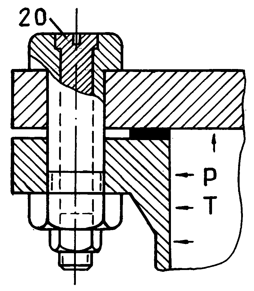

Image

  • Method and devices to limit a creep of mechanical fasteners
  • Method and devices to limit a creep of mechanical fasteners

Examples


Embodiment Construction

—FIG. 3 IS PREFERRED EMBODIMENT

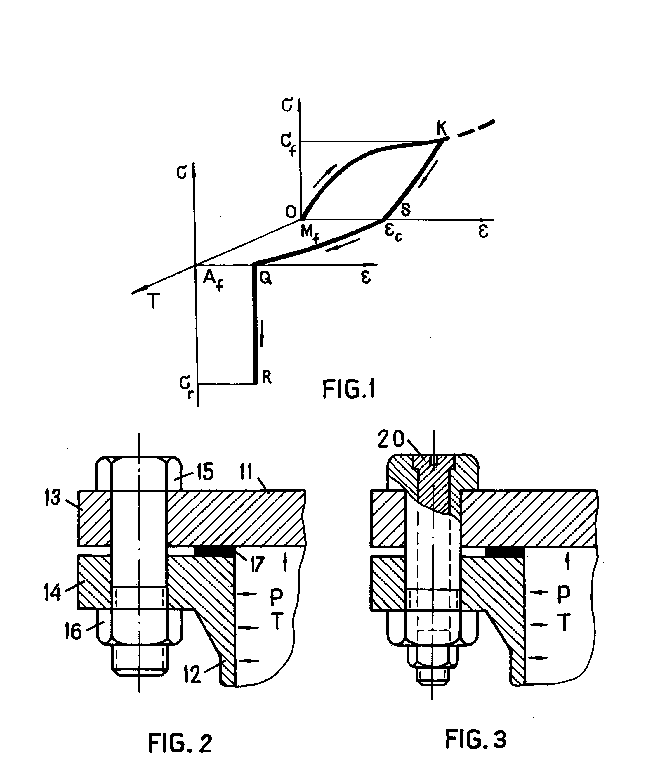
[0035]FIG. 1 is three-dimensional stress-strain-temperature diagram σ-ε-T showing a behavior of power element of shape memory alloy during the formation of shape-memorized deformation along with its constrained recovery. An initial point “O” corresponds to temperature below Mf at which the transformation of martensite finishes. The stress-induced martensite is obtained during loading-unloading of the power element that is presented at the stress-strain diagram σ-ε at the rear graph in FIG. 1. The point K corresponds to the final stress σf before unloading, and the point S corresponds to the final strain εc after unloading.

[0036] The strain εC is a conserved residual shape-memorized deformation of the power element of shape memory alloy. This deformation tries to be recovered during the heating to the temperature Af (point Q at the front graph in FIG. 1 corresponding to austenite state of the power element), but its shape recovery is stopped by rigid c...


PUM


Abstract

A method and devices to limit or to exclude operating creep of mechanical fasteners is disclosed. The method consists in use of mechanical fasteners such as bolts, gaskets, screws, washers and other power elements manufactured from shape memory alloys having temperature interval of martensitic phase transformations corresponding to the operating temperature of industrial equipment. The power elements are previously shape-memorized either to tension or to compression, flexion, torsion, or to their combinations under temperature of martensite state with suitable quantity of conserved residual shape-memorized deformation obtained during loading-unloading of the power elements. Further constrained recovery of shape-memorized deformation under operating temperature generates reactive shape-recovering forces having direction inverse to the direction of operating creep. The process of creep limitation is called “Method of “negative creep”.

Description

CROSS-REFERENCE TO RELATED APPLICATION [0001] Not Applicable FEDERALLY SPONSORED RESEARCH [0002] Not Applicable SEQUENCE LISTING OR PROGRAM [0003] Not Applicable BACKGROUND OF THE INVENTION—FIELD OF INVENTION [0004] This invention relates to mechanical fasteners, specifically to bolted flanged connections with gaskets that have to provide a tight and durable joint between component parts of pressure vessels, piping systems, and other industrial facilities under external and / or internal loadings and operating elevated temperatures. BACKGROUND OF THE INVENTION [0005] One of the most typically used means to obtain the tight and durable joint between component parts of industrial facilities is to connect their pieces with bolted fasteners. These connections have a wide applicability in petrochemical, chemical, aerospace, fossil fuel and nuclear power industries, and others. [0006] There are millions of bolts in critical facilities of cited industries, and the problem of structural durab...

Claims


Application Information

Patent Timeline
Patent Type & Authority Applications(United States)
IPC IPC(8): F02F11/00F16B1/00F16B33/00F16B43/00F16L23/20
CPCF16B1/0014F16B33/006F16B43/00Y10S411/909Y10T403/645Y10T403/21Y10T403/217F16L23/20F16B2200/506F16B2200/77
Inventor EFREMOV, ANATOLY
Owner EFREMOV ANATOLY
Why Eureka
Try Eureka