Self calibrating fan

Active Publication Date: 2005-11-03
MINEBEAMITSUMI INC
View PDF19 Cites 32 Cited by
  • Summary
  • Abstract
  • Description
  • Claims
  • Application Information

AI Technical Summary

Benefits of technology

[0016] The present invention discloses an apparatus and method for self-calibrating a variable-speed fan for use in cooling circuitry found in electronic equipment. The present invention responds to changes in ambient temperature of the area or component to be cooled by micro-adjusting fan speed to accommodate more or less cooling capacity, as needed, thereby maintaining precise temperatures in the subject region or circuit. The fan increases rotation speed of the motor as a function of temperature measured by a temperature-sensing subcircuit such as a thermistor, thermistor array or equivalent means. Unlike related-art fans, changes in fan speed can be made across a continuous spectrum of values, not merely at discrete intervals—thus maximizing cooling capacity while minimizing unwanted effects such as noise and power consumption.
[0017] Additionally, the present invention teaches mechanisms which permit the fan to calculate specific speed values for particular self-calibrated temperatures, and thus adjusting for manufacturing tolerances contained within its constituent electronic components. The fan is placed in a fixed-temperature region when first powered on. An error offset value which compensates for the initial tolerance of the circuitry is then stored in non-volatile memory via a software routine stored in a microcontroller. Subsequent temperature measurements during normal operation mode are then corrected using the stored offset value. Highly precise control over fan speed can thereby be obtained while simultaneously containing manufacturing costs. The self-calibrating fan thereby obviates the need for expensive calibration techniques during the manufacturing stage—such as circuit trimming, using expensive components with low tolerances, or discarding large numbers of unacceptable units—since any tolerance within a reasonable range can be compensated for using the offset value.

Problems solved by technology

Modern electronic devices have a tendency to retain heat when operated for long periods of time, which eventually interferes with proper function of the equipment.
Cooling fans, however, introduce their own set of drawbacks—most notably among them unwanted noise and unnecessary power consumption.
These drawbacks are particularly acute when the fan is required either to run at a single speed or to remain off.
Even designs for variable-speed fans, however, present difficulties in measuring with sufficient accuracy the temperature of the area or circuit to be cooled.
Calibrating measurements over a wide range of temperatures can be difficult and costly—particularly considering that the measurement circuit's componentry is often manufactured to moderate or low tolerances for the sake of cost savings.

Method used


Image

  • Self calibrating fan
  • Self calibrating fan
  • Self calibrating fan

Examples


Embodiment Construction

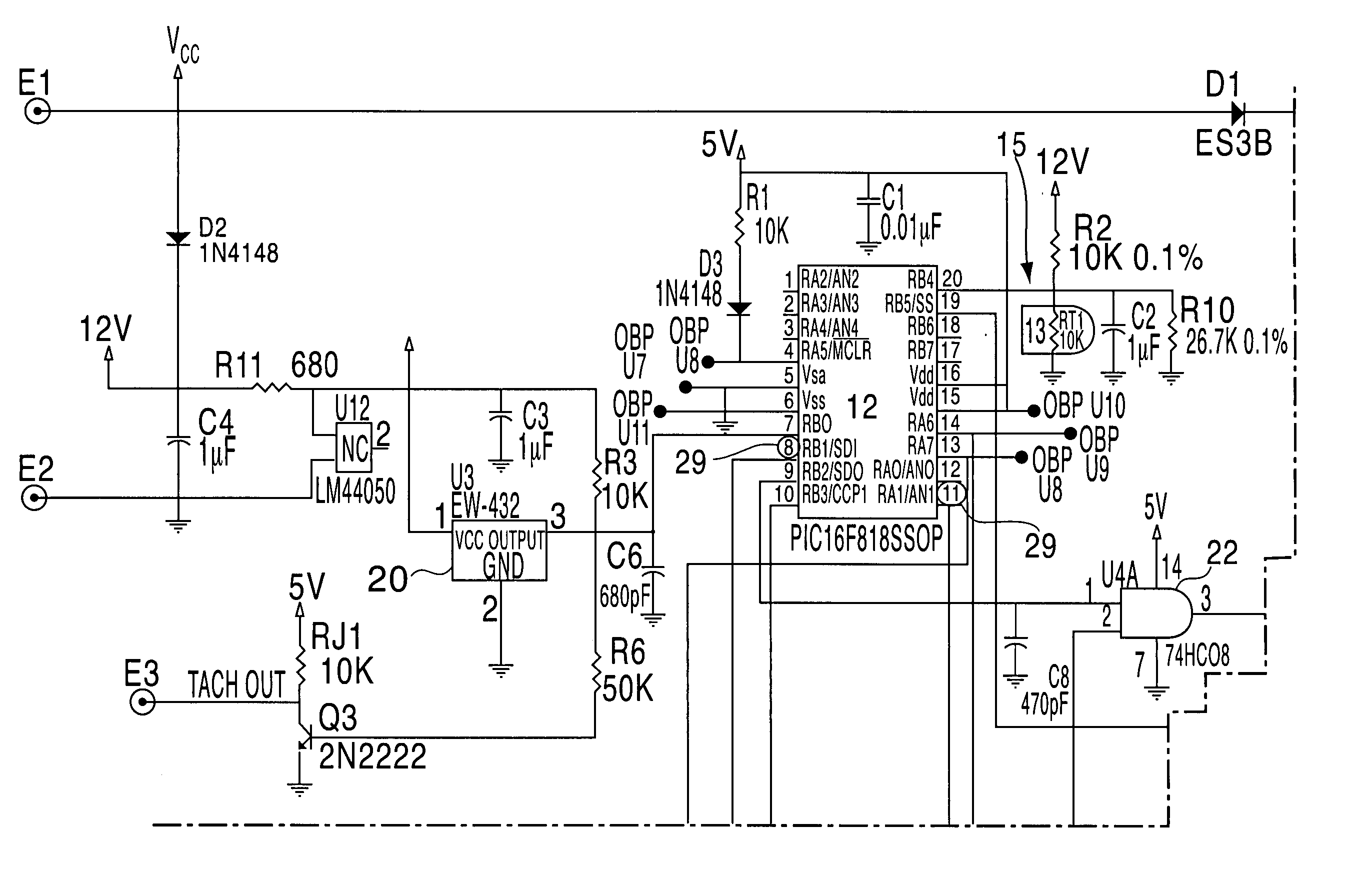
[0022]FIG. 1 describes the claimed device via a schematic diagram of the circuit elements contained therein. A temperature-sensing subcircuit 13 such as a thermistor, thermistor array or other equivalent means, is attached to a microcontroller 12 via a temperature-signal line 15. The microcontroller 12 is also connected to a fan motor 14 via a commutation-signal line 16. The temperature-sensing subcircuit 13 is used for reading temperatures in the region, device or circuit to be cooled. The temperature-signal line 13 transmits to the microcontroller 12 a voltage reading from across the temperature-sensing subcircuit 13. The microcontroller 12 carries out many tasks including but not limited to, determining whether the device has been calibrated or not, storing an offset value to compensate for tolerances within the temperature-sensing subcircuit 13, adjusting the voltage value read from across the temperature-sensing subcircuit 13 to arrive at an adjusted temperature, calculating a ...


PUM


Abstract

A self-calibrating, continuous variable speed fan for use in cooling electronic circuitry is disclosed. Upon initial power-up, in an environment of known temperature, the self-calibrating fan accommodates for the tolerances of its electronic components by reading a voltage from its thermistor array and comparing the actual value to an expected value for the given temperature. The difference is then stored in the non-volatile memory of a microcontroller for use in adjusting future voltage readings from the thermistor array. During normal operation, adjusted readings from the thermistor array are then converted by the microcontroller into a control signal for driving the motor of a cooling fan. A quickly cycling stochastic process between adjustments to fan motor speed and temperature readings is then established, thereby maintaining a high degree of control over the device to be cooled.

Description

BACKGROUND OF THE INVENTION [0001] 1. Field of the Invention [0002] The present invention is directed toward a fan for use in cooling circuitry found in electronic equipment. More particularly, the present invention provides a highly accurate and highly temperature-sensitive electronic cooling fan capable of responding in real time to minor fluctuations in ambient temperature of the region or device to be cooled using cost-effective moderate to low tolerance componentry without resorting to circuit trimming or discarding a large number of units. [0003] 2. Description of the Related Art [0004] Modern electronic devices have a tendency to retain heat when operated for long periods of time, which eventually interferes with proper function of the equipment. Internal cooling systems, such as fans, are therefore required to maintain system integrity and assure proper performance. Cooling fans, however, introduce their own set of drawbacks—most notably among them unwanted noise and unneces...

Claims


Application Information

Patent Timeline
IPC IPC(8): F01D17/00F01D19/02F01D21/12F01D21/14F03B15/00F03D7/00F04D15/00F04D27/02H05K7/20
CPCH05K7/20836F04D27/004Y02B30/70
InventorHARDT, ERIC A.FRANKEL, SCOTT
OwnerMINEBEAMITSUMI INC