Pad adjustable equalizer for two way cable transmission

a technology of equalizer and cable transmission, applied in the field of equalizers, can solve the problems of aggravated signal strength, amplify or equalize return signals, and internet signals traveling in two directions

a technology of equalizer and cable transmission, applied in the field of equalizers, can solve the problems of aggravated signal strength, amplify or equalize return signals, and internet signals traveling in two directions

US20050246755A1Inactive Publication Date: 2005-11-03CABLESERV

Image

  • Pad adjustable equalizer for two way cable transmission
  • Pad adjustable equalizer for two way cable transmission
  • Pad adjustable equalizer for two way cable transmission

Examples


Embodiment Construction

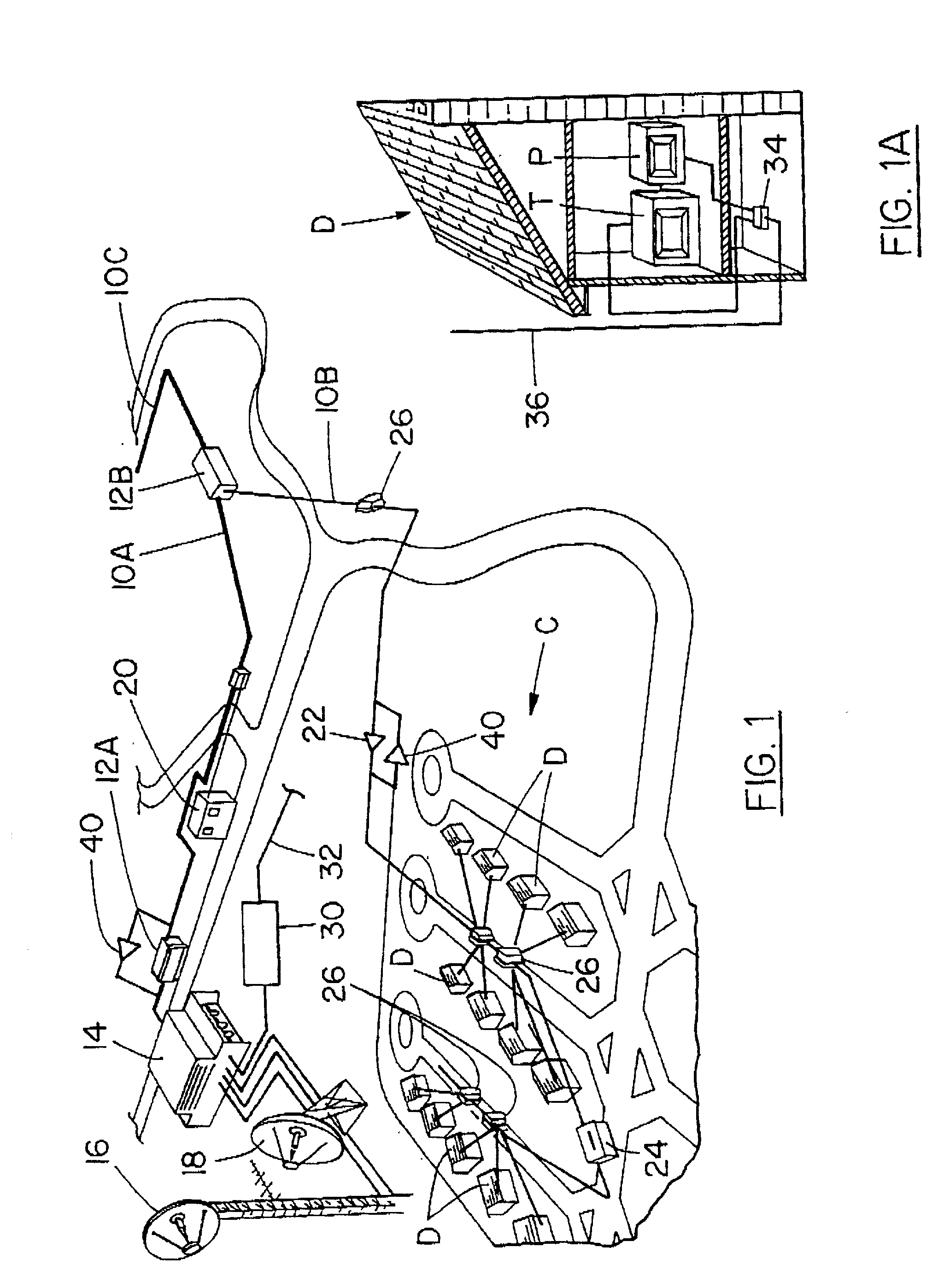
[0032] Referring first of all to FIG. 1, it will be seen that what is represented there is a community indicated generally as C, consisting of a plurality of dwellings indicated as D, and one of the dwellings indicated as D being greatly enlarged and partially cut away.

[0033] Within the cut away enlarged dwelling D it will be seen that the dwelling is provided with a television receiver indicated as T, and a typical personal computer indicated as P.

[0034] It will of course be appreciated that the dwellings, television and personal computer do not form any part of the invention, and are merely represented schematically for the sake of explaining the utility of the invention.

[0035] A coaxial cable distribution line is indicated generally as 10A. It is supplied through a main station 12A, from a head end supply installation 14 with first forward signals, in this case television signals. Further main stations 12B and so on may be located at spaced intervals along the cable 10A, allow...


PUM


Abstract

A forward signal equalizer for a forward amplifier for two-way coaxial cable systems, of the type having a distribution centre distributing forward signals, and having reception facilities for receiving return signals from said cable system, the system having forward amplifiers for receiving forward signals, and having return amplifiers, and the forward signal equalizers are settable to provide varying amplifier specifications, and having receptacles for receiving plug-in equalizer components for varying the specifications of the forward amplifier, the equalizer components having a range of varying performance characteristics so that a component can be selected and plugged in to the forward signal equalizer to produce the performance specifications desired at a predetermined location in the cable system.

Description

[0001] This application is a Continuation-In-Part of U.S. application Ser. No. 09 / 426,624, filing date Oct. 26, 1999 Title: Amplifier and Equalizer for Two-way Cable Transmission and Method, Inventors: Anthony J. Sandaluk. And Viorel Dan, which is a Continuation-In-Part of U.S. Pat. No. 5,990,929, filing date Aug. 14, 1998, Title:Return Amplifier For Two Way Cable Transmission and Method, Inventor: Anthony J. Sandaluk.FIELD OF THE INVENTION [0002] The invention relates to equalizers for use on a coaxial cable transmission system, for equalizing the signal strengths of the forward signals and also of the return signals carried on such system, and to such an equalizer having plug in attenuator components for presetting the performance characteristics of the equalizer to a particular location on the cable system and for a predetermined frequency band. BACKGROUND OF THE INVENTION [0003] Coaxial cable transmission networks for distributing cable television services are in wide use in man...

Claims


Application Information

Patent Timeline
03 Nov 2005
Publication
US20050246755A1
IPC
H04N7/10; H04N7/173
CPC
H04N7/102; H04N7/17309
Inventors
SANDALUK, ANTHONY; DAN, VIOREL