Closed drift ion source

a technology of closed drift ion source and ion thruster, which is applied in the direction of magnetic discharge control, instruments, machines/engines, etc., can solve the problems of affecting the performance of ion sources, poor beam collimation out of sources, and loss of energetic electrons to the side walls

Inactive Publication Date: 2005-11-10
GENERAL PLASMA
View PDF23 Cites 68 Cited by
  • Summary
  • Abstract
  • Description
  • Claims
  • Application Information

AI Technical Summary

Problems solved by technology

These prior art devices suffer from problems of sputter erosion of the closed drift side walls, loss of energetic electrons to the side walls, and poor beam collimation out of the source.
Side wall erosion has deleterious effects on ion source performance including: The source wall inserts, magnetic poles, or other plasma exposed surfaces must be routinely replaced.
Where replacement is not possible in space thruster applications, wall erosion is eventually catastrophic.
This can be a severe problem in space based applications where heat must be dissipated by radiation.
The high temperatures experienced by the side walls requires special, expensive materials.
Ions striking the side walls do not exit the source, reducing source efficiency.
In ion sources operated in the diffuse mode, erosion is particularly problematic if not ruinous.
Other problems generally recognized with prior art ion sources include: Loss of high energy electro

Method used


Image

  • Closed drift ion source
  • Closed drift ion source
  • Closed drift ion source

Examples


Embodiment Construction

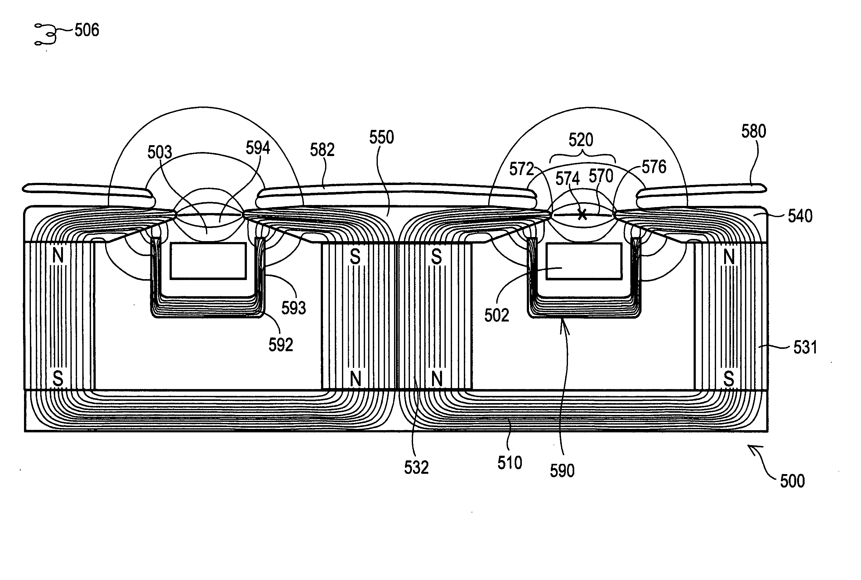
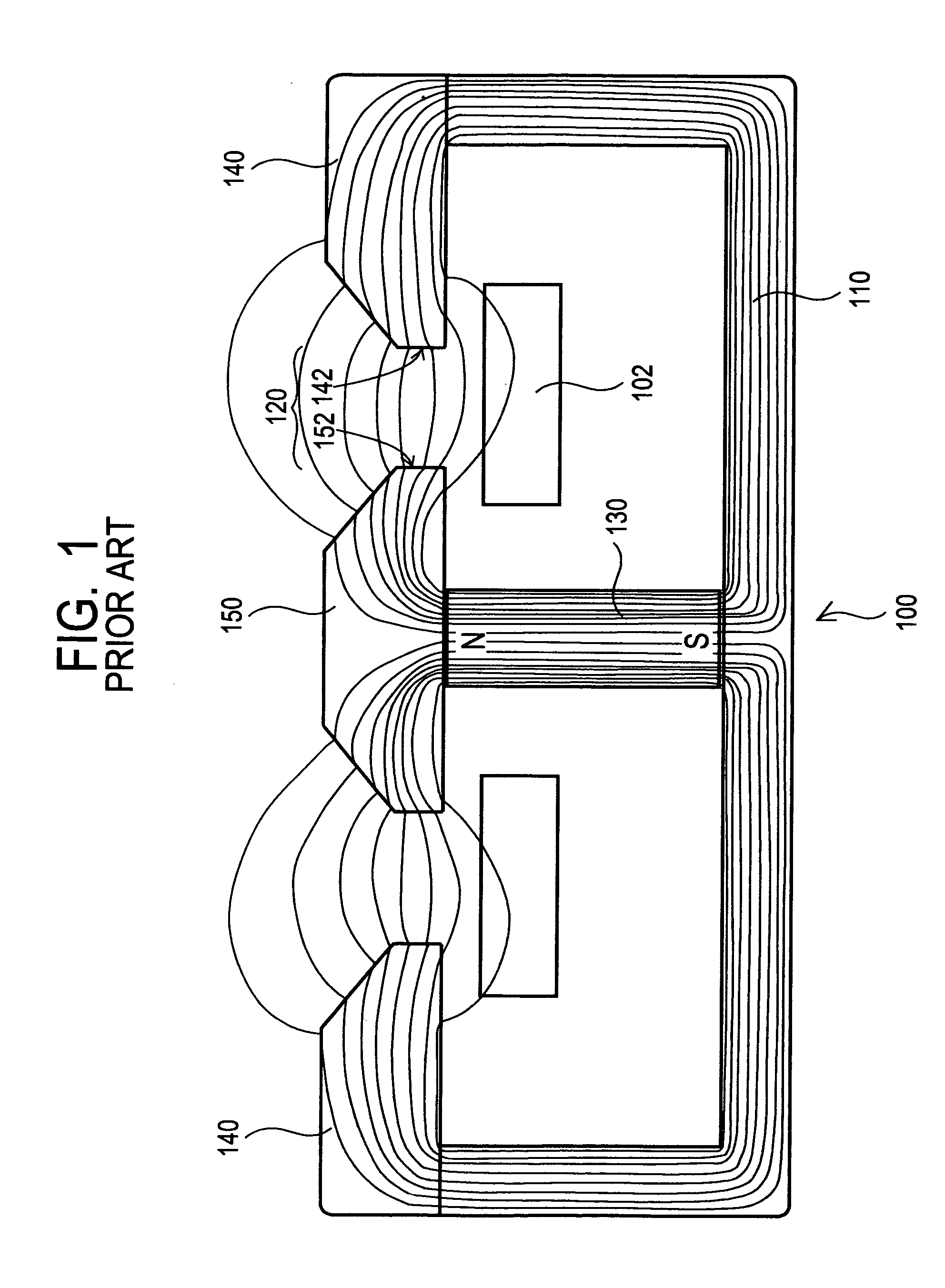
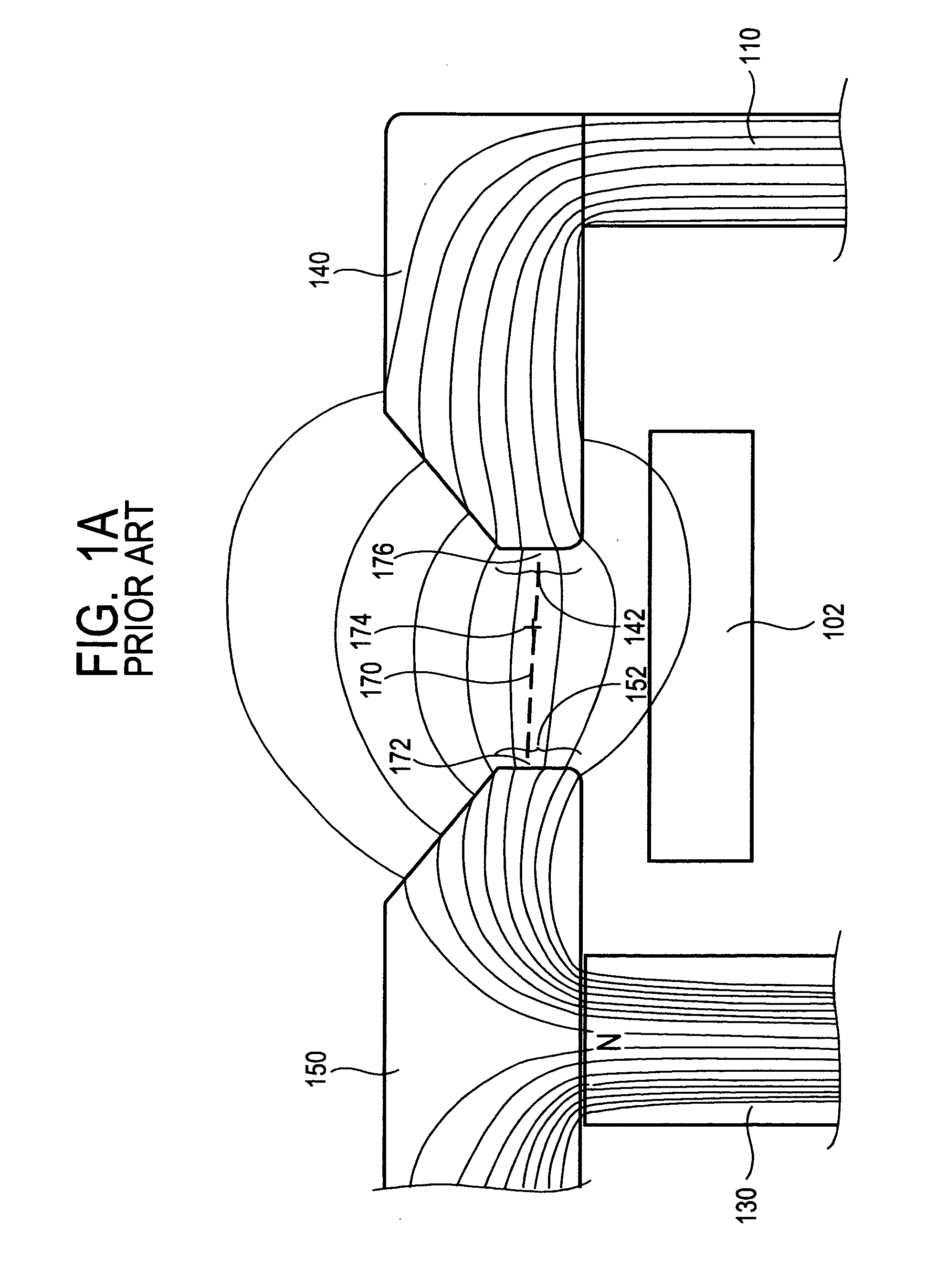
[0062] While the prior art has recognized the problems of existing ion source technology, Applicant's improvements described herein address these prior art problems. Referring to the illustrations, like numerals correspond to like parts depicted in the figures. The invention will be described as embodied various ion source devices to contain, focus, and direct a plasma formed from one or more ionizable gases. The introduction of such one or more ionizable gases into an ion source device, and the formation and ignition of such a plasma is known to one of ordinary skill in the art. This being the case, for purposes of simplicity FIGS. 5, 6, 7, 8, and 9, do not show an input for one or more ionizable gases or a plasma formed therefrom.

[0063]FIG. 5 is a section view of a closed drift ion source showing the magnetic fields of the preferred embodiment. The magnetic field across gap 520 is created by magnet shunt 510, magnets 531 and 532, pole pieces 540 and 550 and magnetic screen 590. I...


PUM


Abstract

A closed drift ion source which includes a channel having an open end, a closed end, and an input port for an ionizable gas. A first magnetic pole is disposed on the open end of the channel and extends therefrom in a first direction. A second magnetic pole disposed on the open end of the channel and extends therefrom in a second direction, where the first direction is opposite to the second direction. The distal ends of the first magnetic pole and the second magnetic pole define a gap comprising the opening in the first end. An anode is disposed within the channel. A primary magnetic field line is disposed between the first magnetic pole and the second magnetic pole, where that primary magnetic field line has a mirror field greater than 2.

Description

CROSS REFERENCE TO RELATED CASES [0001] This application is a Continuation-In-Part application claiming priority from a United States application having Ser. No. 10 / 411,024.FIELD OF THE INVENTION [0002] This invention relates to closed drift ion sources and to closed drift type ion thrusters. More particularly, it includes embodiments that extend the life and efficiency of these devices. BACKGROUND OF THE INVENTION [0003] Closed drift ion sources have been known since Russian ion thrusters for satellite propulsion were reported in the 1960's. These prior art devices suffer from problems of sputter erosion of the closed drift side walls, loss of energetic electrons to the side walls, and poor beam collimation out of the source. [0004] Side wall erosion has deleterious effects on ion source performance including: [0005] The source wall inserts, magnetic poles, or other plasma exposed surfaces must be routinely replaced. Where replacement is not possible in space thruster applications,...

Claims


Application Information

Patent Timeline
IPC IPC(8): F03H1/00H01J3/04H01J27/00H01J33/00H05H1/24
CPCF03H1/0075H05H1/24H01J27/143H05H1/54
Inventor MADOCKS, JOHN
Owner GENERAL PLASMA
Why Eureka
Try Eureka