Plasma display panel

a technology of display panel and plasma, which is applied in the direction of instruments, apparatus for dispensing discrete objects, gas-filled discharge tubes, etc., can solve the problems of serious damage to the electrode, and achieve the effect of a large increase in the aperture ratio and transmittance, and a significant expansion of the discharge area

Inactive Publication Date: 2005-11-10
SAMSUNG SDI CO LTD
View PDF21 Cites 10 Cited by
  • Summary
  • Abstract
  • Description
  • Claims
  • Application Information

AI Technical Summary

Benefits of technology

[0010] The present invention relates to a plasma display panel (PDP) in which aperture ratio and transmittance are greatly increased, the discharge area is significantly enlarged with significant enlargement of a discharge surface, and discharge is uniformly performed in the entire discharge area.

Problems solved by technology

Since the electric charges move directly between the corresponding electrodes in the DC type PDP, there is a problem in that the electrodes are seriously damaged.

Method used


Image

  • Plasma display panel
  • Plasma display panel
  • Plasma display panel

Examples


Embodiment Construction

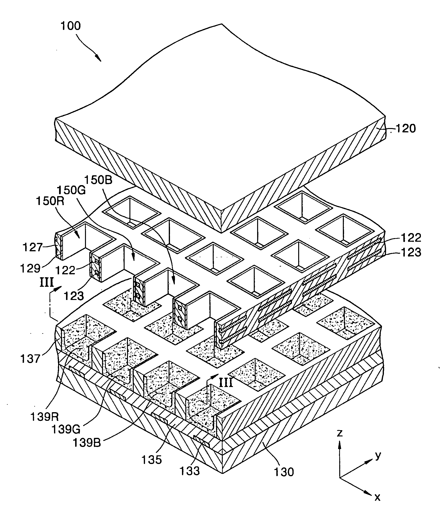
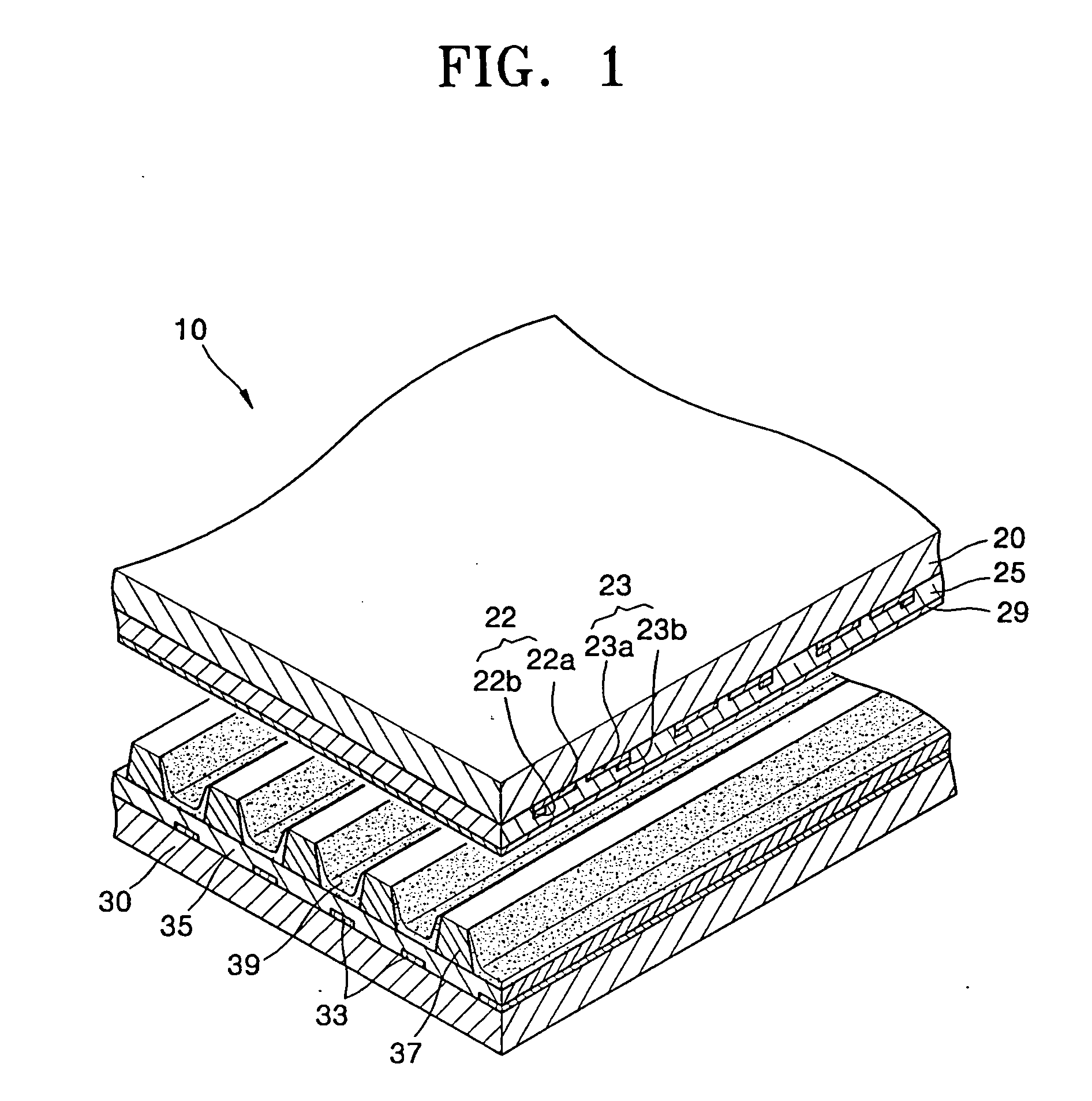
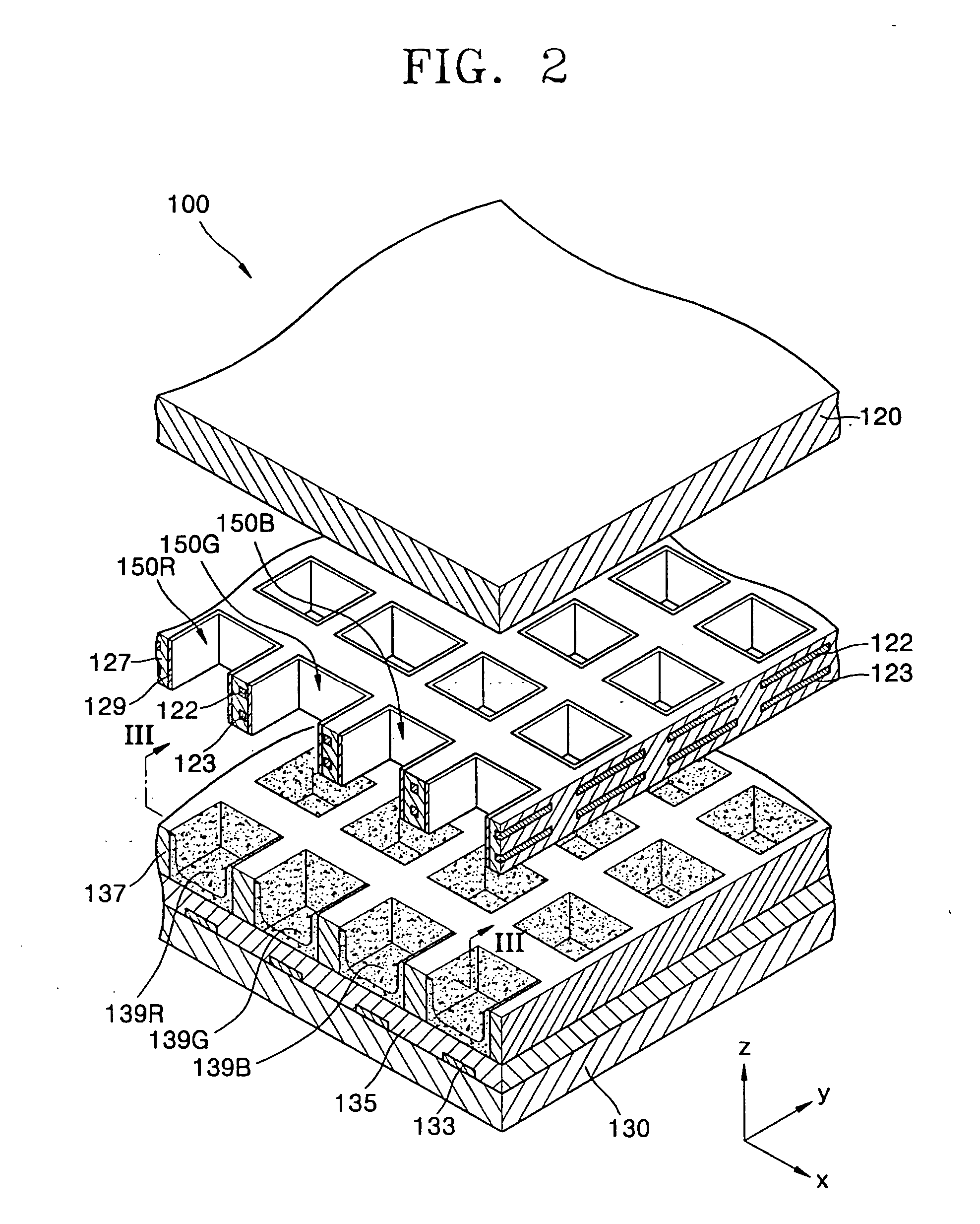
[0024]FIG. 1 is an exploded perspective view of an alternating current (AC) three-electrode surface-discharge plasma display panel (PDP).

[0025] Referring to FIG. 1, an AC type three-electrode surface-discharge PDP 10 includes a front panel 20 and a rear panel 30.

[0026] The rear panel 30 is provided with address electrodes 33 generating address discharge, a rear dielectric layer 35 covering the address electrodes 33, barrier ribs 37 defining discharge cells, and phosphor layers 39 coated on both side surfaces of the barrier ribs 37 and portions of the rear panel 30 in which the barrier ribs 37 are not formed.

[0027] The front panel 20 is disposed to oppose the rear panel 30, and is provided with X and Y electrodes 22 and 23 generating sustain discharge, a front dielectric layer 25 covering the X and Y electrodes 22 and 23, and a protective layer 29. In this case, each X electrode 22 includes a transparent X electrode 22a, and a bus X electrode 22b which is disposed at a side of the...


PUM


Abstract

A plasma display panel (PDP) includes a front panel, a rear panel disposed parallel to the front panel, first barrier ribs formed of a dielectric substance and disposed between the front panel and the rear panel to define a plurality of discharge cells, front discharge electrodes disposed inside the first barrier ribs so as to surround the discharge cells and spaced from the side surfaces of the discharge cells toward interiors of the first barrier ribs by an electrode-burying depth, rear discharge electrodes disposed inside the first barrier ribs so as to surround the discharge cells and spaced from the side surfaces of the discharge cells toward the interiors of the first barrier ribs by an electrode-burying depth at the rear side of the first discharge electrodes, a plurality of phosphor layers disposed inside the discharge cells for receiving ultraviolet rays and emitting visible rays, the phosphor layers having different dielectric constants, and a discharge gas filling the discharge cells. The electrode-burying depth corresponding to discharge cells in which phosphor layers having the lowest dielectric constant are formed is smaller than the electrode-burying depth corresponding to discharge cells in which phosphor layers having a relatively high dielectric constant are formed.

Description

CLAIM OF PRIORITY [0001] This application makes reference to, incorporates the same herein, and claims all benefits accruing under 35 U.S.C. §119 from an application for PLASMA DISPLAY PANEL earlier filed in the Korean Intellectual Property Office on May 7, 2004 and there, duly assigned Serial No. 10-2004-0032202. BACKGROUND OF THE INVENTION [0002] 1. Technical Field [0003] The present invention relates to a plasma display panel (PDP), and more particularly, to a PDP used as a flat display panel in which electrodes are arranged on the opposed surfaces of substrates, discharge gas is filled in a discharge space between the substrates, and an image is displayed using light emitted by ultraviolet rays which are generated in the discharge space with application of a predetermined voltage. [0004] 2. Related Art [0005] In recent years, display apparatuses employing a plasma display panel as a flat display panel have been widely used. Such display apparatuses have excellent characteristics...

Claims


Application Information

Patent Timeline
Patent Type & Authority Applications(United States)
IPC IPC(8): H01J17/04H01J17/49
CPCH01J11/16H01J11/24H01J2211/326H01J11/36H01J11/42H01J11/32G07F9/105G07F11/005G07F11/62
Inventor KWEON, TAE-JOUNG
Owner SAMSUNG SDI CO LTD
Why Eureka
Try Eureka